

152
Coastal Engineering: Theory and Practice
approach channel and protected generally by an island breakwater. And the
material dredged at the trap is pumped directly downdrift by the pipeline
of the dredger.
Alternatively, for large inlets, the dredging is carried ont by a hopper
dredger and the materials are taken to a dredger berth located downdrift
of the inlet from where the materials could be directly pumped, thereby
avoiding the pipeline from Crossing the channel [Fig. 4.32(c)].
4.8.5 Crater — Sink sand transfer System
This technique originally suggested by Inman and Harris [1970] consists of
a hydraulic jet assembly operating from the bottom of the sand crater.
The sand transfer System involves of mouth section, a jet pump, transfer
and delivery pumping of slurry sand mixture facility. As the mouth section
is situated at the lowest point, the entire crater acts as gravity fed for ail
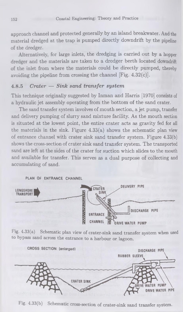
the materials in the sink. Figure 4.33(a) shows the schematic plan view
of entrance channel with crater sink sand transfer System. Figure 4.33(b)
shows the cross-section of crater sink sand transfer System. The transported
sand are left at the sides of the crater for suction which slides to the mouth
and available for transfer. This serves as a dual purpose of collecting and
accumulating of sand.
PLAN OF ENTRANCE CHANNEL
l'ig- 4.33(a) Schematic plan view of crater-sink sand transfer System when used
to bypass sand across the entrance to a harbour or lagoon.
Fig. 4.33(b) Schematic cross-section of crater-sink sand transfer System.
Coastal Engineering: Theory and Practice
approach channel and protected generally by an island breakwater. And the
material dredged at the trap is pumped directly downdrift by the pipeline
of the dredger.
Alternatively, for large inlets, the dredging is carried ont by a hopper
dredger and the materials are taken to a dredger berth located downdrift
of the inlet from where the materials could be directly pumped, thereby
avoiding the pipeline from Crossing the channel [Fig. 4.32(c)].
4.8.5 Crater — Sink sand transfer System
This technique originally suggested by Inman and Harris [1970] consists of
a hydraulic jet assembly operating from the bottom of the sand crater.
The sand transfer System involves of mouth section, a jet pump, transfer
and delivery pumping of slurry sand mixture facility. As the mouth section
is situated at the lowest point, the entire crater acts as gravity fed for ail
the materials in the sink. Figure 4.33(a) shows the schematic plan view
of entrance channel with crater sink sand transfer System. Figure 4.33(b)
shows the cross-section of crater sink sand transfer System. The transported
sand are left at the sides of the crater for suction which slides to the mouth
and available for transfer. This serves as a dual purpose of collecting and
accumulating of sand.
PLAN OF ENTRANCE CHANNEL
l'ig- 4.33(a) Schematic plan view of crater-sink sand transfer System when used
to bypass sand across the entrance to a harbour or lagoon.
Fig. 4.33(b) Schematic cross-section of crater-sink sand transfer System.