

Flow in pressurized conduits 73
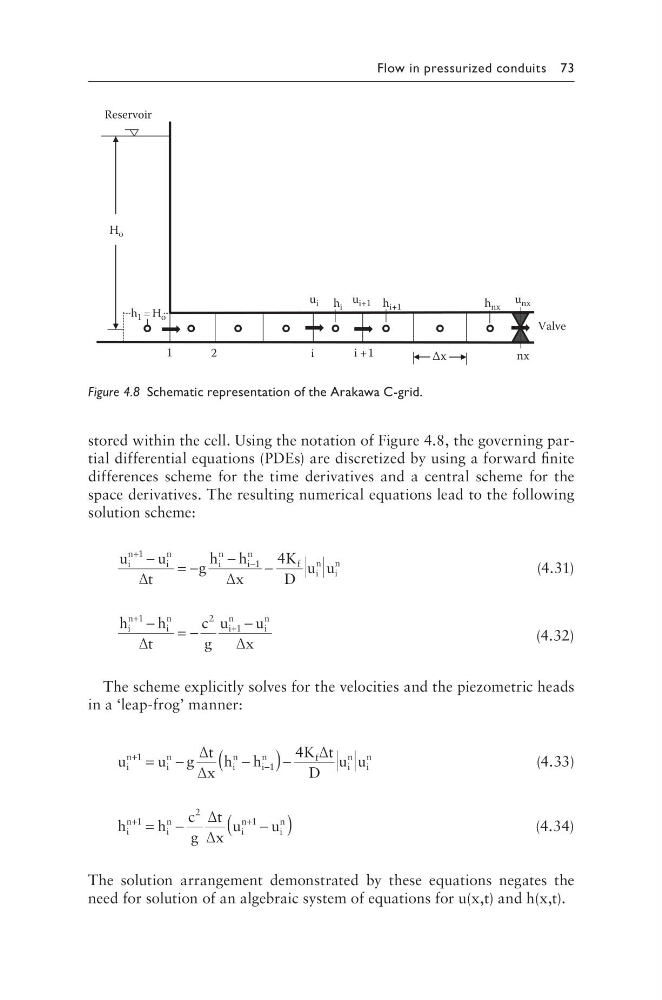
stored within the cell. Using the notation of Figure 4.8, the governing partial differential equations (PDEs) are discretized by using a forward finite
differences scheme for the time derivatives and a central scheme for the
space derivatives. The resulting numerical equations lead to the following
solution scheme:
u
u
t
g
h h
x
K
D
u u
i
n
i
n
i
n
i
n
f
i
n
i
n
+
−
−
= −
−
−
1
1
4
∆
∆
(4.31)
h
h
t
c
g
u
u
x
i
n
i
n
i
n
i
n
+
+
−
= −
−
1
2
1
∆
∆
(4.32)
The scheme explicitly solves for the velocities and the piezometric heads
in a ‘leap-frog’ manner:
u
u g
t
x
h h
K t
D
u u
i
n
i
n
i
n
i
n
f
i
n
i
n
+
−
= −
−
(
)−
1
1
4
∆
∆
∆
(4.33)
h
c
g
t
x
u
u
i
n
i
n
i
n
i
n
+
+
= −
−
(
)
1
2
1
h
∆
∆
(4.34)
The solution arrangement demonstrated by these equations negates the
need for solution of an algebraic system of equations for u(x,t) and h(x,t).
H o
1
2
i
i + 1
nx
u i
u i+1
u nx
h 1 = H o
h i
h i+1
h nx
Δx
Valve
Reservoir
Figure 4.8 Schematic representation of the Arakawa C-grid.
stored within the cell. Using the notation of Figure 4.8, the governing partial differential equations (PDEs) are discretized by using a forward finite
differences scheme for the time derivatives and a central scheme for the
space derivatives. The resulting numerical equations lead to the following
solution scheme:
u
u
t
g
h h
x
K
D
u u
i
n
i
n
i
n
i
n
f
i
n
i
n
+
−
−
= −
−
−
1
1
4
∆
∆
(4.31)
h
h
t
c
g
u
u
x
i
n
i
n
i
n
i
n
+
+
−
= −
−
1
2
1
∆
∆
(4.32)
The scheme explicitly solves for the velocities and the piezometric heads
in a ‘leap-frog’ manner:
u
u g
t
x
h h
K t
D
u u
i
n
i
n
i
n
i
n
f
i
n
i
n
+
−
= −
−
(
)−
1
1
4
∆
∆
∆
(4.33)
h
c
g
t
x
u
u
i
n
i
n
i
n
i
n
+
+
= −
−
(
)
1
2
1
h
∆
∆
(4.34)
The solution arrangement demonstrated by these equations negates the
need for solution of an algebraic system of equations for u(x,t) and h(x,t).
H o
1
2
i
i + 1
nx
u i
u i+1
u nx
h 1 = H o
h i
h i+1
h nx
Δx
Valve
Reservoir
Figure 4.8 Schematic representation of the Arakawa C-grid.