

248 Computational Modelling in Hydraulic and Coastal Engineering
The boundary conditions applied in the case of bubble-generated
flow are as follows:
On the particles-source point a number of particles equal to n p Δt is
introduced in each time step.
On the lateral boundaries the U velocity is related to the excess
pressure head (Δp) as U = ±Δpc p .
On the upper and lower boundaries a zero-flow condition is applied
(V = 0).
The surrogate particles reaching the boundaries of the flow domain
are eliminated and are not included in the subsequent dynamic
computations.
Other data utilized for the simulation were
Pressure waves celerity = 4 m/s
Eddy viscosity = 0.1 m 2 /s
Coordinates of the particle point source: x o = 14.5 m; y o = 1.5 m
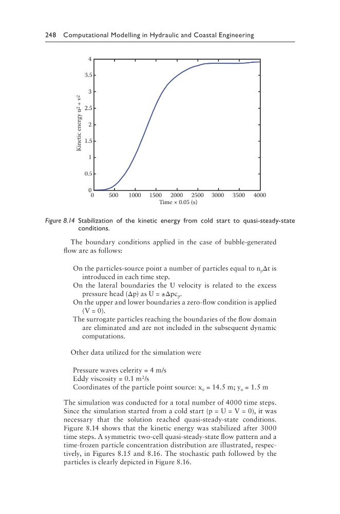
The simulation was conducted for a total number of 4000 time steps.
Since the simulation started from a cold start (p = U = V = 0), it was
necessary that the solution reached quasi-steady-state conditions.
Figure 8.14 shows that the kinetic energy was stabilized after 3000
time steps. A symmetric two-cell quasi-steady-state flow pattern and a
time-frozen particle concentration distribution are illustrated, respectively, in Figures 8.15 and 8.16. The stochastic path followed by the
particles is clearly depicted in Figure 8.16.
4
3
2
1
0
0
3.5
2.5
1.5
0.5
500
1000 1500 2000 2500 3000 3500 4000
Time × 0.05 (s)
Kinetic energy u 2
+ v 2
Figure 8.14 Stabilization of the kinetic energy from cold start to quasi-steady-state
conditions.
The boundary conditions applied in the case of bubble-generated
flow are as follows:
On the particles-source point a number of particles equal to n p Δt is
introduced in each time step.
On the lateral boundaries the U velocity is related to the excess
pressure head (Δp) as U = ±Δpc p .
On the upper and lower boundaries a zero-flow condition is applied
(V = 0).
The surrogate particles reaching the boundaries of the flow domain
are eliminated and are not included in the subsequent dynamic
computations.
Other data utilized for the simulation were
Pressure waves celerity = 4 m/s
Eddy viscosity = 0.1 m 2 /s
Coordinates of the particle point source: x o = 14.5 m; y o = 1.5 m
The simulation was conducted for a total number of 4000 time steps.
Since the simulation started from a cold start (p = U = V = 0), it was
necessary that the solution reached quasi-steady-state conditions.
Figure 8.14 shows that the kinetic energy was stabilized after 3000
time steps. A symmetric two-cell quasi-steady-state flow pattern and a
time-frozen particle concentration distribution are illustrated, respectively, in Figures 8.15 and 8.16. The stochastic path followed by the
particles is clearly depicted in Figure 8.16.
4
3
2
1
0
0
3.5
2.5
1.5
0.5
500
1000 1500 2000 2500 3000 3500 4000
Time × 0.05 (s)
Kinetic energy u 2
+ v 2
Figure 8.14 Stabilization of the kinetic energy from cold start to quasi-steady-state
conditions.