

130 Computational Modelling in Hydraulic and Coastal Engineering
Total length of the system = 10000 m
Equilibrium depth of the upper layer = 10 m
Equilibrium depth of the lower layer = 10 m
The computational discretization steps are ∆x = 200 m and ∆t = 10 s.
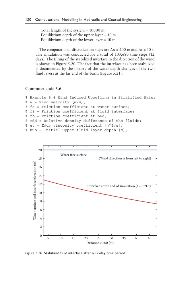
The simulation was conducted for a total of 103,680 time steps (12
days). The tilting of the stabilized interface in the direction of the wind
is shown in Figure 5.20. The fact that the interface has been stabilized
is documented by the history of the water depth changes of the two
fluid layers at the far end of the basin (Figure 5.21).
Computer code 5.6
% Example 5.6 Wind Induced Upwelling in Stratified Water
% w = Wind velocity [m/s];
% fs = Friction coefficient at water surface;
% fi = Friction coefficient at fluid interface;
% fb = Friction coefficient at bed;
% rdd = Relative density difference of the fluids;
% ev = Eddy viscosity coefficient [m^2/s];
% huo = Initial upper fluid layer depth [m];
20
18
16
14
12
10
8
6
4
2
0
5
1 0
1 5
2 0
2 5
3 0
3 5
4 0
4 5
Distance × 200 (m)
Water free surface
(Wind direction is from left to right)
Interface at the end of simulation (t = nt*Dt)
Water surface and interface elevation (m)
Figure 5.20 Stabilized fluid interface after a 12-day time period.
Total length of the system = 10000 m
Equilibrium depth of the upper layer = 10 m
Equilibrium depth of the lower layer = 10 m
The computational discretization steps are ∆x = 200 m and ∆t = 10 s.
The simulation was conducted for a total of 103,680 time steps (12
days). The tilting of the stabilized interface in the direction of the wind
is shown in Figure 5.20. The fact that the interface has been stabilized
is documented by the history of the water depth changes of the two
fluid layers at the far end of the basin (Figure 5.21).
Computer code 5.6
% Example 5.6 Wind Induced Upwelling in Stratified Water
% w = Wind velocity [m/s];
% fs = Friction coefficient at water surface;
% fi = Friction coefficient at fluid interface;
% fb = Friction coefficient at bed;
% rdd = Relative density difference of the fluids;
% ev = Eddy viscosity coefficient [m^2/s];
% huo = Initial upper fluid layer depth [m];
20
18
16
14
12
10
8
6
4
2
0
5
1 0
1 5
2 0
2 5
3 0
3 5
4 0
4 5
Distance × 200 (m)
Water free surface
(Wind direction is from left to right)
Interface at the end of simulation (t = nt*Dt)
Water surface and interface elevation (m)
Figure 5.20 Stabilized fluid interface after a 12-day time period.