

STRUCTURAL MASS, DAMPING, AND RESTRAINT
41
structural element. The bending stiffness of the brace is derived from elementary
beam theory and is
El
k, = 192
(2.41)
Here, /cj can be interpreted as the latéral force that, when applied to the
midspan, will produce a static deflection of v = 1 at midspan. The structurefluid damping is assumed to be linear-viscous which, referring to équation (2.23),
has the following form:
ci = c£ + C'DpI —
(2-42)
(a) TUBULARCROSSBRACE
(SIDE VIEW)
CROSS SECTION
(b) DEFLECTION ENVELOPE
(TOP VIEW)
m
(c) LUMPED MASS MODEL
(TOP VIEW)
(d) STRUCTURAL MODEL
(TOP VIEW)
(e) FREE BODY SKETCH
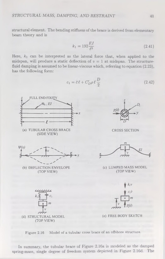
Figure 2.16 Model of a tubular cross brace of an offshore structure.
In summary, the tubular brace of Figure 2.16a is modeled as the damped
spring-mass, single degree of freedom System depicted in Figure 2.16d. 1 he
41
structural element. The bending stiffness of the brace is derived from elementary
beam theory and is
El
k, = 192
(2.41)
Here, /cj can be interpreted as the latéral force that, when applied to the
midspan, will produce a static deflection of v = 1 at midspan. The structurefluid damping is assumed to be linear-viscous which, referring to équation (2.23),
has the following form:
ci = c£ + C'DpI —
(2-42)
(a) TUBULARCROSSBRACE
(SIDE VIEW)
CROSS SECTION
(b) DEFLECTION ENVELOPE
(TOP VIEW)
m
(c) LUMPED MASS MODEL
(TOP VIEW)
(d) STRUCTURAL MODEL
(TOP VIEW)
(e) FREE BODY SKETCH
Figure 2.16 Model of a tubular cross brace of an offshore structure.
In summary, the tubular brace of Figure 2.16a is modeled as the damped
spring-mass, single degree of freedom System depicted in Figure 2.16d. 1 he