

308
BEHAVIOR OF PILES SUPPORTING OFFSHORE STRUCTURES
Problem Description
The problem is illustrated in Figure 11.12, which shows a plane truss or beat
from an offshore platform. A template or jacket, which consists of a welded pipe
framework, is first set on the océan floor. In this particular case the legs of the
jacket are assumed to penetrate into the soft surface soil. The pénétration is 140
in.; mud sills are set below the bottom bracing to keep the jacket from sinking
further.
After the jacket is set, the piles are stabbed into the jacket legs and driven
to a predetermined pénétration. The annular space between the pile and the
jacket is then grouted. (Some designers prefer not to use a jacket-leg extension
and not to grout the annular space in order to reduce the bending moment at
the bottom panel points. In this case, the wall thickness of the pile must be
greater than in the case being considered.)
(a)
(b)
h = 240 in.
- Mudline
dia
140 in14,117 in?
Pile plus
jacket leg: I
Pile: lp = 375 in?
E = 30X106
(steel)
psi
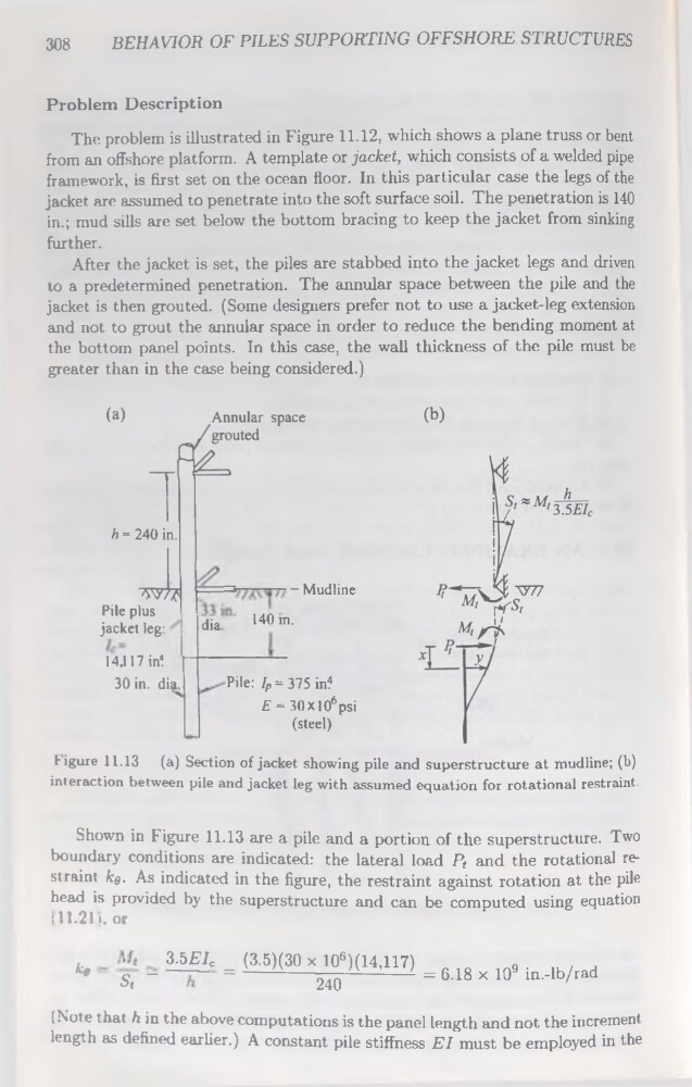
Figure 11.13 (a) Section of jacket showing pile and superstructure at mudline; (b)
interaction between pile and jacket leg with assumed équation for rotational restraint.
Shown in Figure 11.13 are a pile and a portion of the superstructure. Two
boundary conditions are indicated: the latéral load Pf and the rotational restraint kg. As indicated in the figure, the restraint against rotation at the pile
head is provided by the superstructure and can be computed using équation
(11.21). or
3.5EIC
(3.5)(30 x 106)(14,117)
„
o9 .
.
*» ■ S, - — *------ ------ 240
= 618 x 10 ln-lb/tad
(Note that h in the above computations is the panel length and not the incrément
length as defined earlier.) A constant pile stiffness El must be employed in the
BEHAVIOR OF PILES SUPPORTING OFFSHORE STRUCTURES
Problem Description
The problem is illustrated in Figure 11.12, which shows a plane truss or beat
from an offshore platform. A template or jacket, which consists of a welded pipe
framework, is first set on the océan floor. In this particular case the legs of the
jacket are assumed to penetrate into the soft surface soil. The pénétration is 140
in.; mud sills are set below the bottom bracing to keep the jacket from sinking
further.
After the jacket is set, the piles are stabbed into the jacket legs and driven
to a predetermined pénétration. The annular space between the pile and the
jacket is then grouted. (Some designers prefer not to use a jacket-leg extension
and not to grout the annular space in order to reduce the bending moment at
the bottom panel points. In this case, the wall thickness of the pile must be
greater than in the case being considered.)
(a)
(b)
h = 240 in.
- Mudline
dia
140 in14,117 in?
Pile plus
jacket leg: I
Pile: lp = 375 in?
E = 30X106
(steel)
psi
Figure 11.13 (a) Section of jacket showing pile and superstructure at mudline; (b)
interaction between pile and jacket leg with assumed équation for rotational restraint.
Shown in Figure 11.13 are a pile and a portion of the superstructure. Two
boundary conditions are indicated: the latéral load Pf and the rotational restraint kg. As indicated in the figure, the restraint against rotation at the pile
head is provided by the superstructure and can be computed using équation
(11.21). or
3.5EIC
(3.5)(30 x 106)(14,117)
„
o9 .
.
*» ■ S, - — *------ ------ 240
= 618 x 10 ln-lb/tad
(Note that h in the above computations is the panel length and not the incrément
length as defined earlier.) A constant pile stiffness El must be employed in the