

SINGLE PILES UNDER AXIAL LOADING
291
estimation of the relative density and friction angle is usually made from the
blow counts found in the field.
11.2
DESIGN OF SINGLE PILES UNDER AXIAL LOADING
Single piles are found in onshore structures and occasionally in an offshore structure. But most offshore structures are founded on groups of piles. If the piles are
four or five diameters apart, pile-soil-piles interaction is negligible and the piles
can be designed as if they were isolated. If the spacing is doser, an efficiency
factor is employed to reduce the capacity of piles in the group. The mechanics
of the transfer of load from the pile to the soil for the single pile can be modified
to include a réduction coefficient.
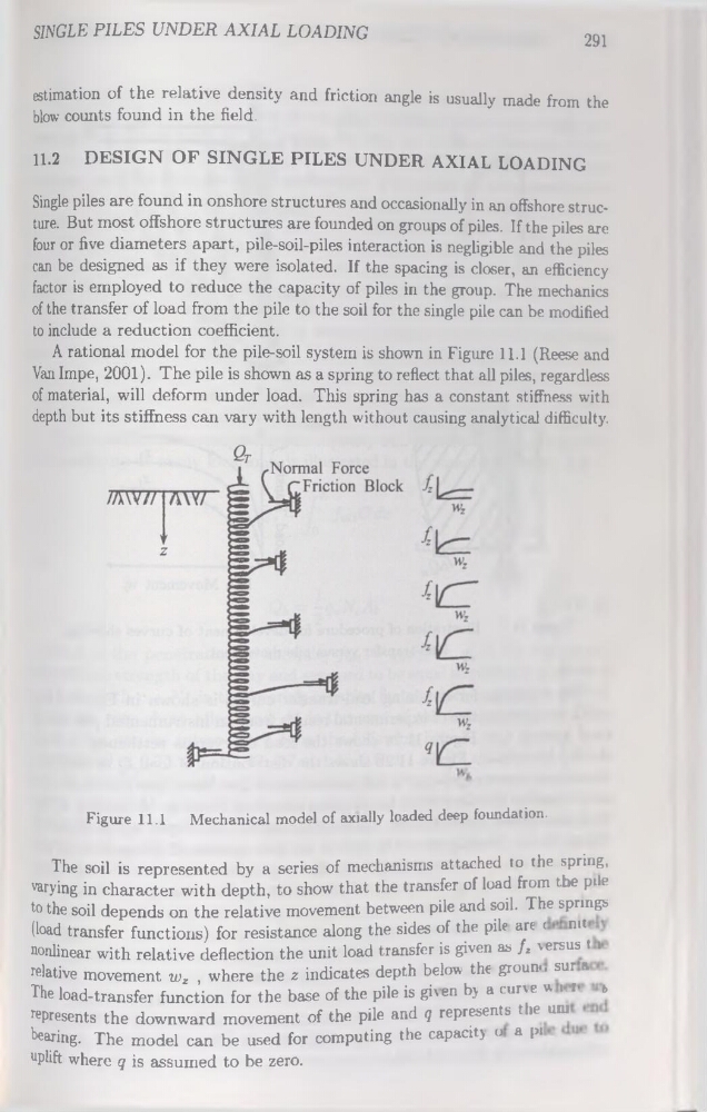
A rational model for the pile-soil System is shown in Figure 11.1 (Reese and
Van Impe, 2001). The pile is shown as a spring to reflect that ail piles, regardless
of material, will deform under load. This spring has a constant stiffness with
depth but its stiffness can vary with length without causing analytical difficulty.
Figure 11.1 Mechanical model of axially loaded deep foundation.
The soil is represented by a sériés of mechanisms attached to the spring,
varying in character with depth, to show that the transfer of load from tbe pde
to the soil dépends on the relative movement between pile and soil. The springs
(load transfer functions) for résistance along the sides of the pile are t nit
nonlinear with relative deflection the unit load transfer is given as fz versus t i
relative movement wz , where the z indicates depth below the groun<< sur a
The load-transfer function for the base of the pile is given by a curve w i.r
b
represents the downward movement of the pile and q represents the um
bearing. The model can be used for computing the capacity o a pi
uplift where q is assumed to be zéro.
291
estimation of the relative density and friction angle is usually made from the
blow counts found in the field.
11.2
DESIGN OF SINGLE PILES UNDER AXIAL LOADING
Single piles are found in onshore structures and occasionally in an offshore structure. But most offshore structures are founded on groups of piles. If the piles are
four or five diameters apart, pile-soil-piles interaction is negligible and the piles
can be designed as if they were isolated. If the spacing is doser, an efficiency
factor is employed to reduce the capacity of piles in the group. The mechanics
of the transfer of load from the pile to the soil for the single pile can be modified
to include a réduction coefficient.
A rational model for the pile-soil System is shown in Figure 11.1 (Reese and
Van Impe, 2001). The pile is shown as a spring to reflect that ail piles, regardless
of material, will deform under load. This spring has a constant stiffness with
depth but its stiffness can vary with length without causing analytical difficulty.
Figure 11.1 Mechanical model of axially loaded deep foundation.
The soil is represented by a sériés of mechanisms attached to the spring,
varying in character with depth, to show that the transfer of load from tbe pde
to the soil dépends on the relative movement between pile and soil. The springs
(load transfer functions) for résistance along the sides of the pile are t nit
nonlinear with relative deflection the unit load transfer is given as fz versus t i
relative movement wz , where the z indicates depth below the groun<< sur a
The load-transfer function for the base of the pile is given by a curve w i.r
b
represents the downward movement of the pile and q represents the um
bearing. The model can be used for computing the capacity o a pi
uplift where q is assumed to be zéro.