

266
CONTINUOUS SYSTEMS
Trans verse Excitation
The undamped motion of a uniform Bernoulli-Euler beam with negligible
longitudinal tension (P = 0) is given by équation (10.12), or
d*v
_ d2v
.
(10.69)
Of practical interest is a beam or pipeline of length t supported at the ends
only, according to one of the six sets of boundary or end conditions defined in
Table 10.1.
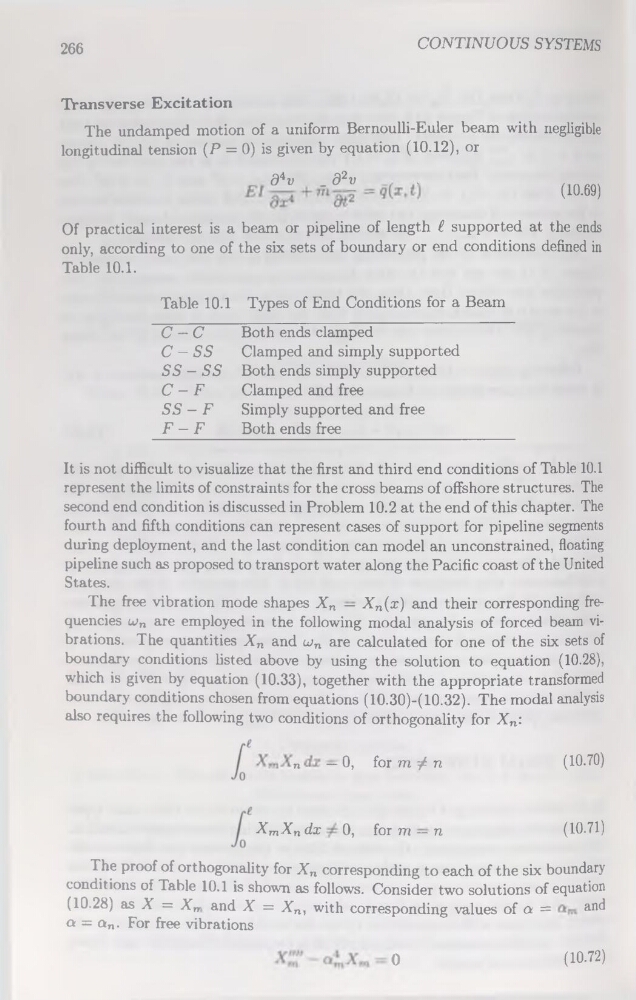
Table 10.1 Types of End Conditions for a Beam
C — C
Both ends clamped
C — SS
Clamped and simply supported
SS - SS Both ends simply supported
C — F
Clamped and free
SS - F
Simply supported and free
F - F
Both ends free
It is not difficult to visualize that the first and third end conditions of Table 10.1
represent the limits of constraints for the cross beams of offshore structures. The
second end condition is discussed in Problem 10.2 at the end of this chapter. The
fourth and fifth conditions can represent cases of support for pipeline segments
during deployment, and the last condition can model an unconstrained, floating
pipeline such as proposed to transport water along the Pacific coast of the United
States.
The free vibration mode shapes Xn — Xn(x) and their corresponding frequencies u)n are employed in the following modal analysis of forced beam vibrations. The quantities Xn and uin are calculated for one of the six sets of
boundary conditions listed above by using the solution to équation (10.28),
which is given by équation (10.33), together with the appropriate transformed
boundary conditions chosen from équations (10.30)-(10.32). The modal analysis
also requires the following two conditions of orthogonality for Xn:
n
— 0,
(10.70)
XmXn dx 0, for m — n
(10.71)
for m / n
The proof of orthogonality for Xn corresponding to each of the six boundary
conditions of Table 10.1 is shown as follows. Consider two solutions of équation
(10.28) as X = Xm and X = Xn, with corresponding values of o =
and
o = an. For free vibrations
— 0
(10.72)
CONTINUOUS SYSTEMS
Trans verse Excitation
The undamped motion of a uniform Bernoulli-Euler beam with negligible
longitudinal tension (P = 0) is given by équation (10.12), or
d*v
_ d2v
.
(10.69)
Of practical interest is a beam or pipeline of length t supported at the ends
only, according to one of the six sets of boundary or end conditions defined in
Table 10.1.
Table 10.1 Types of End Conditions for a Beam
C — C
Both ends clamped
C — SS
Clamped and simply supported
SS - SS Both ends simply supported
C — F
Clamped and free
SS - F
Simply supported and free
F - F
Both ends free
It is not difficult to visualize that the first and third end conditions of Table 10.1
represent the limits of constraints for the cross beams of offshore structures. The
second end condition is discussed in Problem 10.2 at the end of this chapter. The
fourth and fifth conditions can represent cases of support for pipeline segments
during deployment, and the last condition can model an unconstrained, floating
pipeline such as proposed to transport water along the Pacific coast of the United
States.
The free vibration mode shapes Xn — Xn(x) and their corresponding frequencies u)n are employed in the following modal analysis of forced beam vibrations. The quantities Xn and uin are calculated for one of the six sets of
boundary conditions listed above by using the solution to équation (10.28),
which is given by équation (10.33), together with the appropriate transformed
boundary conditions chosen from équations (10.30)-(10.32). The modal analysis
also requires the following two conditions of orthogonality for Xn:
n
— 0,
(10.70)
XmXn dx 0, for m — n
(10.71)
for m / n
The proof of orthogonality for Xn corresponding to each of the six boundary
conditions of Table 10.1 is shown as follows. Consider two solutions of équation
(10.28) as X = Xm and X = Xn, with corresponding values of o =
and
o = an. For free vibrations
— 0
(10.72)