

256
CONTINUOUS SYSTEMS
Cross Brace : El, m, L
(a)
(b)
(c)
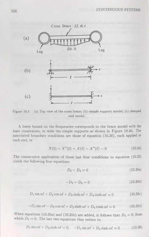
Figure 10.4 (a) Top view of the cross brace; (b) simple support model; (c) clamped
end model.
A lower bound on the frequencies corresponds to the brace model with the
least constraints, or with the simple supports as shown in Figure 10.4b. The
associated boundary conditions are those of équation (10.30), each applied at
each end, or
X(0) = X"(0) = X(£) = X"(£) = 0
(10.34)
The consecutive application of these last four conditions to équation (10.33)
yields the following four équations:
D2 + D4 = 0
(10.35a)
-D2 + D4 = 0
(10.35b)
Di sin
+ £)2 cos at + D3 sinh al + D4 cosh al — 0
(10.35c)
—Di sin al — D2 cos at + D3 sinh at + D4 cosh at = 0
(10.35d)
WTien équations (10.35a) and (10.35b) are added, it follows that D4 = 0, from
which D2 = 0. The last two équations thus reduce to
D, sin at + D3 sinh at = 0; -Dj sin at + D3 sinh at = 0
(10.36)
CONTINUOUS SYSTEMS
Cross Brace : El, m, L
(a)
(b)
(c)
Figure 10.4 (a) Top view of the cross brace; (b) simple support model; (c) clamped
end model.
A lower bound on the frequencies corresponds to the brace model with the
least constraints, or with the simple supports as shown in Figure 10.4b. The
associated boundary conditions are those of équation (10.30), each applied at
each end, or
X(0) = X"(0) = X(£) = X"(£) = 0
(10.34)
The consecutive application of these last four conditions to équation (10.33)
yields the following four équations:
D2 + D4 = 0
(10.35a)
-D2 + D4 = 0
(10.35b)
Di sin
+ £)2 cos at + D3 sinh al + D4 cosh al — 0
(10.35c)
—Di sin al — D2 cos at + D3 sinh at + D4 cosh at = 0
(10.35d)
WTien équations (10.35a) and (10.35b) are added, it follows that D4 = 0, from
which D2 = 0. The last two équations thus reduce to
D, sin at + D3 sinh at = 0; -Dj sin at + D3 sinh at = 0
(10.36)