

254
CONTINUOUS SYSTEMS
where the subscript n on the frequency parameter is a reminder that there are
multiple frequencies. For each characteristic value 7 there is a frequency cjn and
a corresponding mode shape X — Xn given by équations (10.18) and (10.22),
where D\ — Cn and D? — 0. That is
Xn = Cnsin^, n=l,2,...
(10.23)
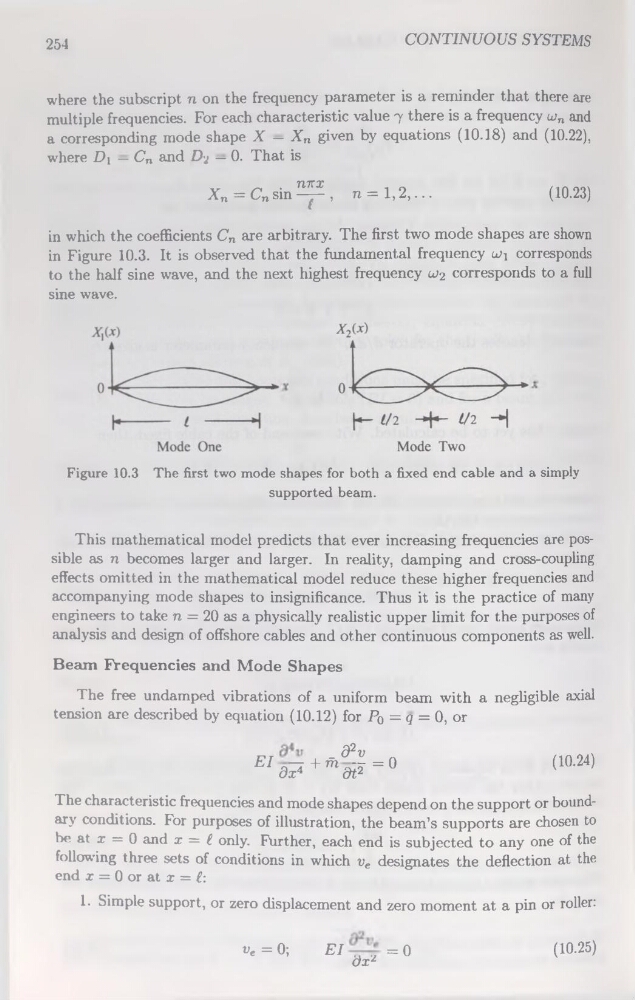
in which the coefficients Cn are arbitrary. The first two mode shapes are shown
in Figure 10.3. It is observed that the fondamental frequency luj corresponds
to the half sine wave, and the next highest frequency u>2 corresponds to a full
sine wave.
Figure 10.3 The first two mode shapes for both a fixed end cable and a simply
supported beam.
This mathematical model predicts that ever increasing frequencies are possible as n becomes larger and larger. In reality, damping and cross-coupling
effects omitted in the mathematical model reduce these higher frequencies and
accompanying mode shapes to insignificance. Thus it is the practice of many
engineers to take n = 20 as a physically realistic upper limit for the purposes of
analysis and design of offshore cables and other continuons components as well.
Beam Frequencies and Mode Shapes
The free undamped vibrations of a uniform beam with a negligible axial
tension are described by équation (10.12) for Po = q = 0, or
_ d2v
BId?+mdë=°
(10.24)
The characteristic frequencies and mode shapes dépend on the support or boundary conditions. For purposes of illustration, the beam’s supports are chosen to
be at x = 0 and x = f. only. Further, each end is subjected to any one of the
following three sets of conditions in which ve désignâtes the deflection at the
end x = 0 or at x = £:
1. Simple support, or zéro displacement and zéro moment at a pin or roller:
«e = 0;
El
= 0
dxz
(10.25)
CONTINUOUS SYSTEMS
where the subscript n on the frequency parameter is a reminder that there are
multiple frequencies. For each characteristic value 7 there is a frequency cjn and
a corresponding mode shape X — Xn given by équations (10.18) and (10.22),
where D\ — Cn and D? — 0. That is
Xn = Cnsin^, n=l,2,...
(10.23)
in which the coefficients Cn are arbitrary. The first two mode shapes are shown
in Figure 10.3. It is observed that the fondamental frequency luj corresponds
to the half sine wave, and the next highest frequency u>2 corresponds to a full
sine wave.
Figure 10.3 The first two mode shapes for both a fixed end cable and a simply
supported beam.
This mathematical model predicts that ever increasing frequencies are possible as n becomes larger and larger. In reality, damping and cross-coupling
effects omitted in the mathematical model reduce these higher frequencies and
accompanying mode shapes to insignificance. Thus it is the practice of many
engineers to take n = 20 as a physically realistic upper limit for the purposes of
analysis and design of offshore cables and other continuons components as well.
Beam Frequencies and Mode Shapes
The free undamped vibrations of a uniform beam with a negligible axial
tension are described by équation (10.12) for Po = q = 0, or
_ d2v
BId?+mdë=°
(10.24)
The characteristic frequencies and mode shapes dépend on the support or boundary conditions. For purposes of illustration, the beam’s supports are chosen to
be at x = 0 and x = f. only. Further, each end is subjected to any one of the
following three sets of conditions in which ve désignâtes the deflection at the
end x = 0 or at x = £:
1. Simple support, or zéro displacement and zéro moment at a pin or roller:
«e = 0;
El
= 0
dxz
(10.25)