

EQUATIONS OF MOTION: GENERAL FORM
203
basic beam éléments, the junction fixity (in this case, welded joints), and the
value of Young s modulus, the cross-sectional area, and the cross-sectional area
moment of inertia for each beam element in the plane frame. In this example,
the deck can be modeled as a rigid body, or a beam with high flexural stiffness
compared to that of the supporting structural éléments. Note that a computer
analysis requires units for the geometry and material properties, and that any
compatible set of units can be used. Thus, the unit displacements can be 1
m or 1 ft, for instance, depending on whether the SI or the traditional English
units are employed.
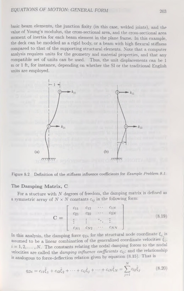
Figure 8.2 Définition of the stiffness influence coefficients for Example Problem 8.1.
The Damping Matrix, C
For a stucture with N degrees of freedom, the damping matrix is defined as
a symmetric array of N x N constants ctJ in the following form:
en
C12
••• cin
Cni Cpj2 •" CNN .
In this analysis, the damping force qoz for 1
structural node coordinate £t is
assumed to be a linear combination of the generalized coordinate veiocities £
t = 1,2,... , N. The constants relating the nodal damping forces to the nodal
veiocities are called the damping influence coefficients ctJ; and the relationship
is analogous to force-deflection relation given by équation (8.15). That is
N
qDi=Ctxti + Ci2€2 + • • • + C^j + ’ ■ ■+
=
>=1
203
basic beam éléments, the junction fixity (in this case, welded joints), and the
value of Young s modulus, the cross-sectional area, and the cross-sectional area
moment of inertia for each beam element in the plane frame. In this example,
the deck can be modeled as a rigid body, or a beam with high flexural stiffness
compared to that of the supporting structural éléments. Note that a computer
analysis requires units for the geometry and material properties, and that any
compatible set of units can be used. Thus, the unit displacements can be 1
m or 1 ft, for instance, depending on whether the SI or the traditional English
units are employed.
Figure 8.2 Définition of the stiffness influence coefficients for Example Problem 8.1.
The Damping Matrix, C
For a stucture with N degrees of freedom, the damping matrix is defined as
a symmetric array of N x N constants ctJ in the following form:
en
C12
••• cin
Cni Cpj2 •" CNN .
In this analysis, the damping force qoz for 1
structural node coordinate £t is
assumed to be a linear combination of the generalized coordinate veiocities £
t = 1,2,... , N. The constants relating the nodal damping forces to the nodal
veiocities are called the damping influence coefficients ctJ; and the relationship
is analogous to force-deflection relation given by équation (8.15). That is
N
qDi=Ctxti + Ci2€2 + • • • + C^j + ’ ■ ■+
=
>=1