

EQUATIONS OF MOTION: GENERAL FORM
199
The Mass Matrix, M
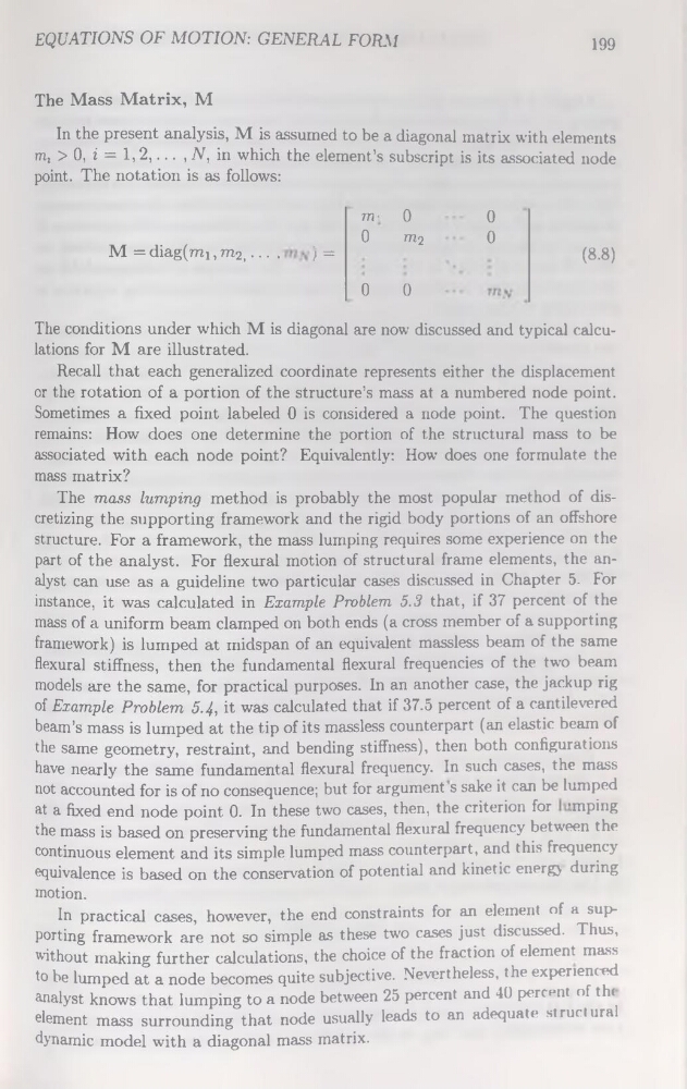
In the présent analysis, M is assumed to be a diagonal matrix with éléments
m, > 0, i = 1,2,... , N, in which the element’s subscript is its associated node
point. The notation is as follows:
M = diag(mi, m2,... .
) =
m-, 0
0
m?
(8-8)
0
0
0
0
The conditions under which M is diagonal are now discussed and typical calculations for M are illustrated.
Recall that each generalized coordinate represents either the displacement
or the rotation of a portion of the structure’s mass at a numbered node point.
Sometimes a fixed point labeled 0 is considered a node point. The question
remains: How does one détermine the portion of the structural mass to be
associated with each node point? Equivalently: How does one formulate the
mass matrix?
The mass lumping method is probably the most popular method of discretizing the supporting framework and the rigid body portions of an offshore
structure. For a framework, the mass lumping requires some expérience on the
part of the analyst. For flexural motion of structural frame éléments, the analyst can use as a guideline two particular cases discussed in Chapter 5. For
instance, it was calculated in Example Problem 5.3 that, if 37 percent of the
mass of a uniform beam clamped on both ends (a cross member of a supporting
framework) is lumped at midspan of an équivalent massless beam of the same
flexural stiffness, then the fundamental flexural frequencies of the two beam
models are the same, for practical purposes. In an another case, the jackup rig
of Example Problem 5-4, it was calculated that if 37.5 percent of a cantilevered
beam’s mass is lumped at the tip of its massless counterpart (an elastic beam of
the same geometry, restraint, and bending stiffness), then both configurations
hâve nearly the same fundamental flexural frequency. In such cases, the mass
not accounted for is of no conséquence; but for argument s sake it can be lumped
at a fixed end node point 0. In these two cases, then, the criterion for ’.mping
the mass is based on preserving the fundamental flexural frequency between the
continuons element and its simple lumped mass counterpart, and this frequency
équivalence is based on the conservation of potential and kinetic energy during
motion.
In practical cases, however, the end constraints for an element of a supporting framework are not so simple as these two cases just discussed. Thus,
without making further calculations, the choice of the fraction of element mass
to be lumped at a node becomes quite subjective. Nevertheless, the experienced
analyst knows that lumping to a node between 25 percent and 40 percent of t ht
element mass surrounding that node usually leads to an adéquate structural
dynamic model with a diagonal mass matrix.
199
The Mass Matrix, M
In the présent analysis, M is assumed to be a diagonal matrix with éléments
m, > 0, i = 1,2,... , N, in which the element’s subscript is its associated node
point. The notation is as follows:
M = diag(mi, m2,... .
) =
m-, 0
0
m?
(8-8)
0
0
0
0
The conditions under which M is diagonal are now discussed and typical calculations for M are illustrated.
Recall that each generalized coordinate represents either the displacement
or the rotation of a portion of the structure’s mass at a numbered node point.
Sometimes a fixed point labeled 0 is considered a node point. The question
remains: How does one détermine the portion of the structural mass to be
associated with each node point? Equivalently: How does one formulate the
mass matrix?
The mass lumping method is probably the most popular method of discretizing the supporting framework and the rigid body portions of an offshore
structure. For a framework, the mass lumping requires some expérience on the
part of the analyst. For flexural motion of structural frame éléments, the analyst can use as a guideline two particular cases discussed in Chapter 5. For
instance, it was calculated in Example Problem 5.3 that, if 37 percent of the
mass of a uniform beam clamped on both ends (a cross member of a supporting
framework) is lumped at midspan of an équivalent massless beam of the same
flexural stiffness, then the fundamental flexural frequencies of the two beam
models are the same, for practical purposes. In an another case, the jackup rig
of Example Problem 5-4, it was calculated that if 37.5 percent of a cantilevered
beam’s mass is lumped at the tip of its massless counterpart (an elastic beam of
the same geometry, restraint, and bending stiffness), then both configurations
hâve nearly the same fundamental flexural frequency. In such cases, the mass
not accounted for is of no conséquence; but for argument s sake it can be lumped
at a fixed end node point 0. In these two cases, then, the criterion for ’.mping
the mass is based on preserving the fundamental flexural frequency between the
continuons element and its simple lumped mass counterpart, and this frequency
équivalence is based on the conservation of potential and kinetic energy during
motion.
In practical cases, however, the end constraints for an element of a supporting framework are not so simple as these two cases just discussed. Thus,
without making further calculations, the choice of the fraction of element mass
to be lumped at a node becomes quite subjective. Nevertheless, the experienced
analyst knows that lumping to a node between 25 percent and 40 percent of t ht
element mass surrounding that node usually leads to an adéquate structural
dynamic model with a diagonal mass matrix.