

EQUATIONS OF MOTION: GENERAL FORM
197
at location 1 and the horizontal bracings at location 2 hâve negligible rotations.
Choose
and v2 as the horizontal displacements from the equilibrium State of
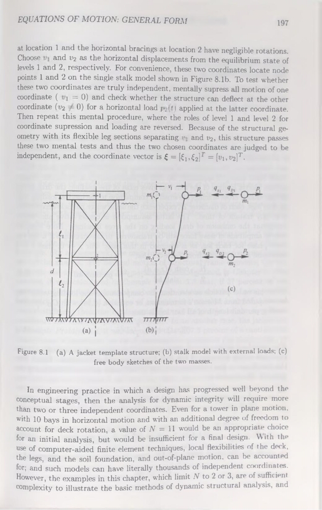
levels 1 and 2, respectively. For convenience, these two coordinates locate node
points 1 and 2 on the single stalk model shown in Figure 8.1b. To test whether
these two coordinates are truly independent, mentally supress ail motion of one
coordinate (
= 0) and check whether the structure can deflect at the other
coordinate (v2 0) for a horizontal load ;>..i » | applied at the latter coordinate.
Then repeat this mental procedure, where the rôles of level 1 and level 2 for
coordinate supression and loading are reversed. Because of the structural geometry with its flexible leg sections separating r and v2, this structure passes
these two mental tests and thus the two chosen coordinates are judged to be
independent, and the coordinate vector is £ = [Ci, £2]F = [t'nt’a]7'Figure 8.1 (a) A jacket template structure; (b) stalk model with external loads; (c)
free body sketches of the two masses.
In engineering practice in which a design has progressed well beyond the
conceptual stages, then the analysis for dynamic integrity will require more
than two or three independent coordinates. Even for a tower in plane motion,
with 10 bays in horizontal motion and with an additional degree of freedom to
account for deck rotation, a value of N = 11 would be an appropriate choice
for an initial analysis, but would be insufficient for a final design. With the
use of computer-aided finite element techniques, local flexibilities of the deck,
the legs, and the soil foundation, and out-of-plane motion, can be accounted
for; and such models can hâve literally thousands of independent coordinates.
However, the examples in this chapter, which limit N to 2 or 3, are of sufficient
complexity to illustrate the basic methods of dynamic structural analysis, and
197
at location 1 and the horizontal bracings at location 2 hâve negligible rotations.
Choose
and v2 as the horizontal displacements from the equilibrium State of
levels 1 and 2, respectively. For convenience, these two coordinates locate node
points 1 and 2 on the single stalk model shown in Figure 8.1b. To test whether
these two coordinates are truly independent, mentally supress ail motion of one
coordinate (
= 0) and check whether the structure can deflect at the other
coordinate (v2 0) for a horizontal load ;>..i » | applied at the latter coordinate.
Then repeat this mental procedure, where the rôles of level 1 and level 2 for
coordinate supression and loading are reversed. Because of the structural geometry with its flexible leg sections separating r and v2, this structure passes
these two mental tests and thus the two chosen coordinates are judged to be
independent, and the coordinate vector is £ = [Ci, £2]F = [t'nt’a]7'Figure 8.1 (a) A jacket template structure; (b) stalk model with external loads; (c)
free body sketches of the two masses.
In engineering practice in which a design has progressed well beyond the
conceptual stages, then the analysis for dynamic integrity will require more
than two or three independent coordinates. Even for a tower in plane motion,
with 10 bays in horizontal motion and with an additional degree of freedom to
account for deck rotation, a value of N = 11 would be an appropriate choice
for an initial analysis, but would be insufficient for a final design. With the
use of computer-aided finite element techniques, local flexibilities of the deck,
the legs, and the soil foundation, and out-of-plane motion, can be accounted
for; and such models can hâve literally thousands of independent coordinates.
However, the examples in this chapter, which limit N to 2 or 3, are of sufficient
complexity to illustrate the basic methods of dynamic structural analysis, and