

Technical aspects of data acquisition and display
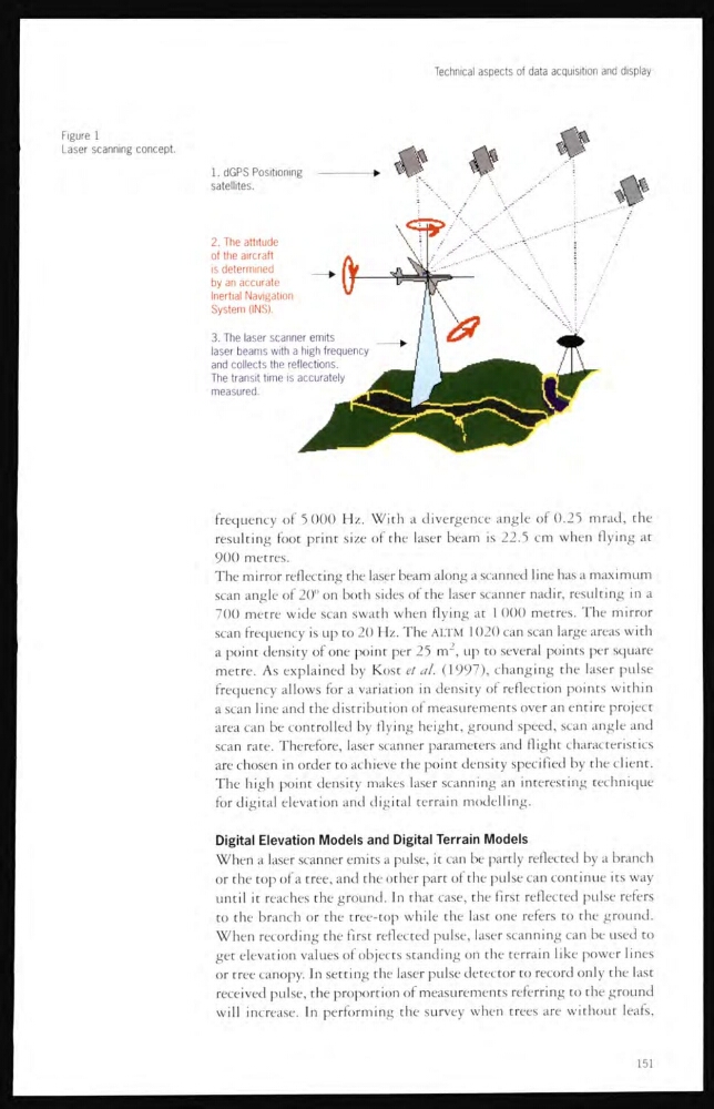
Figure 1
Laser scanning concept.
frequency of 5 000 Hz. With a divergence angle of 0.25 mrad, the
resulting foot print size of the laser beam is 22.5 cm when flying at
900 metres.
The mirror reflecting the laser beam along a scanned line has a maximum
scan angle of 20° on both sides of the laser scanner nadir, resulting in a
700 metre wide scan swath when flying at 1 000 metres. The mirror
scan frequency is up to 20 Hz. The ALTM 1020 can scan large areas with
a point density of one point per 25 m 2 , up to several points per square
metre. As explained by Kost et al. (1997), changing the laser pulse
frequency allows for a variation in density of reflection points within
a scan line and the distribution of measurements over an entire project
area can be controlled by flying height, ground speed, scan angle and
scan rate. Therefore, laser scanner parameters and flight characteristics
are chosen in order to achieve the point density specified by the client.
The high point density makes laser scanning an interesting technique
for digital elevation and digital terrain modelling.
Digital Elevation Models and Digital Terrain Models
When a laser scanner emits a pulse, it can be partly reflected by a branch
or the top of a tree, ancl the other part of the pulse can continue its way
until it reaches the ground. In that case, the first reflected pulse refers
to the branch or the tree-top while the last one refers to the ground.
When recording the first reflected pulse, laser scanning can be used to
get elevation values of objects standing on the terrain like power lines
or tree canopy. In setting the laser pulse detector to record only the last
received pulse, the proportion of measurements referring to the ground
will increase. In performing the survey when trees are without leafs,
151
Figure 1
Laser scanning concept.
frequency of 5 000 Hz. With a divergence angle of 0.25 mrad, the
resulting foot print size of the laser beam is 22.5 cm when flying at
900 metres.
The mirror reflecting the laser beam along a scanned line has a maximum
scan angle of 20° on both sides of the laser scanner nadir, resulting in a
700 metre wide scan swath when flying at 1 000 metres. The mirror
scan frequency is up to 20 Hz. The ALTM 1020 can scan large areas with
a point density of one point per 25 m 2 , up to several points per square
metre. As explained by Kost et al. (1997), changing the laser pulse
frequency allows for a variation in density of reflection points within
a scan line and the distribution of measurements over an entire project
area can be controlled by flying height, ground speed, scan angle and
scan rate. Therefore, laser scanner parameters and flight characteristics
are chosen in order to achieve the point density specified by the client.
The high point density makes laser scanning an interesting technique
for digital elevation and digital terrain modelling.
Digital Elevation Models and Digital Terrain Models
When a laser scanner emits a pulse, it can be partly reflected by a branch
or the top of a tree, ancl the other part of the pulse can continue its way
until it reaches the ground. In that case, the first reflected pulse refers
to the branch or the tree-top while the last one refers to the ground.
When recording the first reflected pulse, laser scanning can be used to
get elevation values of objects standing on the terrain like power lines
or tree canopy. In setting the laser pulse detector to record only the last
received pulse, the proportion of measurements referring to the ground
will increase. In performing the survey when trees are without leafs,
151