

10. ELECTRIC ORGANS
353
+ + + + + + + +
A
( = )
- - -
+ + + + + + + +
Resting, no current flow
+ + + + + + + +
+ + I +
Upper face active
D
7 External potential
Indifferent
electrode
Face 2
r
r - - - - - - - - - -
' Monopolarly recorded j
to active face
'
C
1 potential external
L-----7---i
t
I active face
I
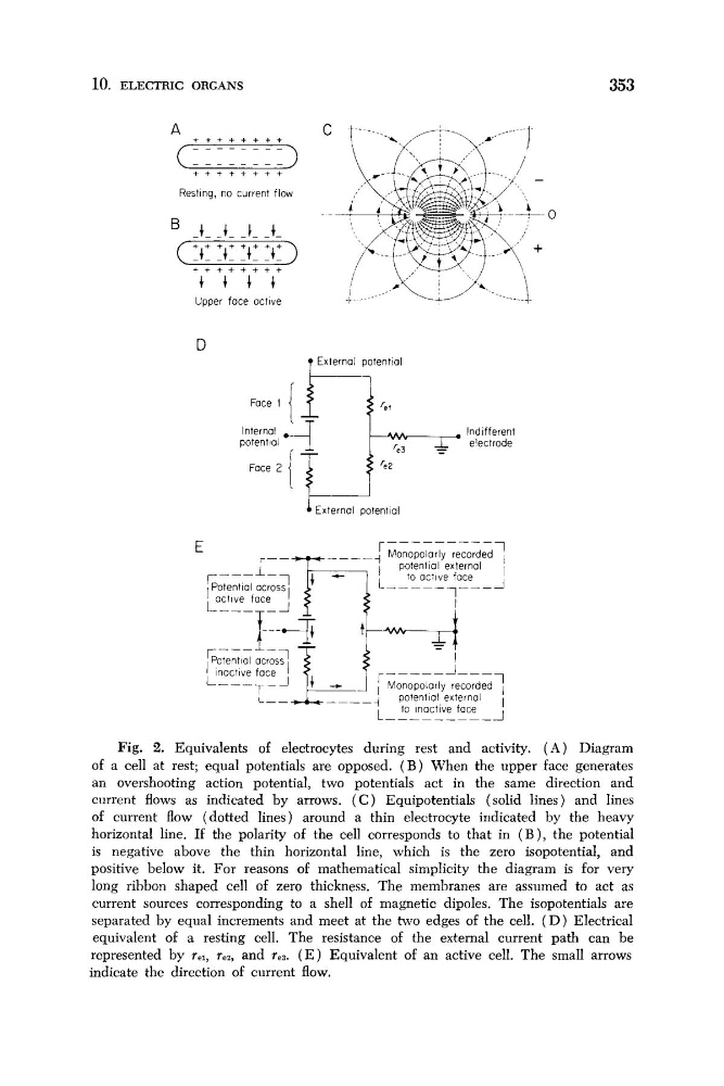
Fig. 2. Equivalents of electrocytes during rest and activity. ( A ) Diagram
of a cell at rest; equal potentials are opposed. ( B ) When the upper face generates
an overshooting action potential, two potentials act in the same direction and
current flows as indicated by arrows. ( C ) Equipotentials (solid lines) and lines
of current flow (dotted lines) around a thin electrocyte indicated by the heavy
horizontal line. If the polarity of the cell corresponds to that in ( B ), the potential
is negative above the thin horizontal line, which is the zero isopotential, and
positive below it. For reasons of mathematical simplicity the diagram is for very
long ribbon shaped cell of zero thickness. The membranes are assumed to act as
current sources corresponding to a shell of magnetic dipoles. The isopotentials are
separated by equal increments and meet at the two edges of the cell. ( D ) Electrical
equivalent of a resting cell. The resistance of the external current path can be
represented by re,, rez, and res. ( E ) Equivalent of an active cell. The small arrows
indicate the direction of current flow.
353
+ + + + + + + +
A
( = )
- - -
+ + + + + + + +
Resting, no current flow
+ + + + + + + +
+ + I +
Upper face active
D
7 External potential
Indifferent
electrode
Face 2
r
r - - - - - - - - - -
' Monopolarly recorded j
to active face
'
C
1 potential external
L-----7---i
t
I active face
I
Fig. 2. Equivalents of electrocytes during rest and activity. ( A ) Diagram
of a cell at rest; equal potentials are opposed. ( B ) When the upper face generates
an overshooting action potential, two potentials act in the same direction and
current flows as indicated by arrows. ( C ) Equipotentials (solid lines) and lines
of current flow (dotted lines) around a thin electrocyte indicated by the heavy
horizontal line. If the polarity of the cell corresponds to that in ( B ), the potential
is negative above the thin horizontal line, which is the zero isopotential, and
positive below it. For reasons of mathematical simplicity the diagram is for very
long ribbon shaped cell of zero thickness. The membranes are assumed to act as
current sources corresponding to a shell of magnetic dipoles. The isopotentials are
separated by equal increments and meet at the two edges of the cell. ( D ) Electrical
equivalent of a resting cell. The resistance of the external current path can be
represented by re,, rez, and res. ( E ) Equivalent of an active cell. The small arrows
indicate the direction of current flow.