

W
P
0
-
10
20
cm
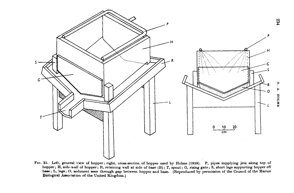
FIG. 35. Left. gmeral view of hopper; right, cross-section of hopper used by Holme (1959). P, pipes supplying jets along top of
hopper; H, sidr-wdl of hoppex; R. retaining wall at side of base (B) ; T, spout; G, rising gate; S, short legs supporting hopper off
b w ; L. legs : 0. scdiment awn through gap between hopper and base. (Reproduced by permission of the Council of the Marine
@iological ,%sawciation of the United Kingdom.)
P
0
-
10
20
cm
FIG. 35. Left. gmeral view of hopper; right, cross-section of hopper used by Holme (1959). P, pipes supplying jets along top of
hopper; H, sidr-wdl of hoppex; R. retaining wall at side of base (B) ; T, spout; G, rising gate; S, short legs supporting hopper off
b w ; L. legs : 0. scdiment awn through gap between hopper and base. (Reproduced by permission of the Council of the Marine
@iological ,%sawciation of the United Kingdom.)