

Experimental Design and Quality Assurance
203
dimension of optical apertures (some are small) vary amongst sensors and some optical
designs also include internal reference measurement of the emitted light to compensate
for aging and temperature dependences of the high-efficient LEDs (TriOS). Examples of
specifications that manufacturers employ for NOM fluorometers are shown in Table 6.1.
Note that the listing of instruments does not equate to an endorsement by the authors. This
compilation merely serves as a reference of some commonly used fluorescence sensors.
6.3.5 Data Output
Beyond options of sensor configuration, there are also choices between passive or programmable sensors and between analog or digital data outputs. The output of any sensor
should be thoroughly examined. If using an analog output, it is recommended that signal degradation be considered especially if the sensor is further than 10 m from the data
logging device. High-quality communication-grade cable should always be used, and the
resistivity of the cable product known. A good alternative is to choose an instrument with
a digital readout which aids in preserving signal integrity, assuming an appropriate signal
cable is utilized, and can be transmitted reliably over the distances required. Alternatively,
internal logging of fluorescence measurements can also be conducted.
6.4 Calibration and Correction Procedures
This section is a compilation of regularly practiced calibration methods for field sensors
found in the literature. Readers are encouraged to consult with the standard operating
350
20
40
Percent Transmittance
60
80
100
CWL
CWL
CWL
Peak Transmittance
Average Transmittance
FWHM
Effective Bandwith ~10 nm
FWHM
Effective Bandwith ~50 nm
½
Peak
Height
Interference Filter
Combined Cutoff Filters
Produce Bandpass Filters
Absorptive Filter
Shortpass
Blocking Filter
400
450
500
Wavelength (nm)
550
600
650
700
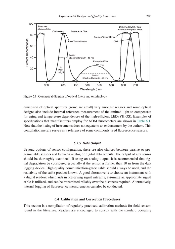
Figure 6.8. Conceptual diagram of optical filters and terminology.
203
dimension of optical apertures (some are small) vary amongst sensors and some optical
designs also include internal reference measurement of the emitted light to compensate
for aging and temperature dependences of the high-efficient LEDs (TriOS). Examples of
specifications that manufacturers employ for NOM fluorometers are shown in Table 6.1.
Note that the listing of instruments does not equate to an endorsement by the authors. This
compilation merely serves as a reference of some commonly used fluorescence sensors.
6.3.5 Data Output
Beyond options of sensor configuration, there are also choices between passive or programmable sensors and between analog or digital data outputs. The output of any sensor
should be thoroughly examined. If using an analog output, it is recommended that signal degradation be considered especially if the sensor is further than 10 m from the data
logging device. High-quality communication-grade cable should always be used, and the
resistivity of the cable product known. A good alternative is to choose an instrument with
a digital readout which aids in preserving signal integrity, assuming an appropriate signal
cable is utilized, and can be transmitted reliably over the distances required. Alternatively,
internal logging of fluorescence measurements can also be conducted.
6.4 Calibration and Correction Procedures
This section is a compilation of regularly practiced calibration methods for field sensors
found in the literature. Readers are encouraged to consult with the standard operating
350
20
40
Percent Transmittance
60
80
100
CWL
CWL
CWL
Peak Transmittance
Average Transmittance
FWHM
Effective Bandwith ~10 nm
FWHM
Effective Bandwith ~50 nm
½
Peak
Height
Interference Filter
Combined Cutoff Filters
Produce Bandpass Filters
Absorptive Filter
Shortpass
Blocking Filter
400
450
500
Wavelength (nm)
550
600
650
700
Figure 6.8. Conceptual diagram of optical filters and terminology.