

Optical Spectroscopy Instrumentation Design
163
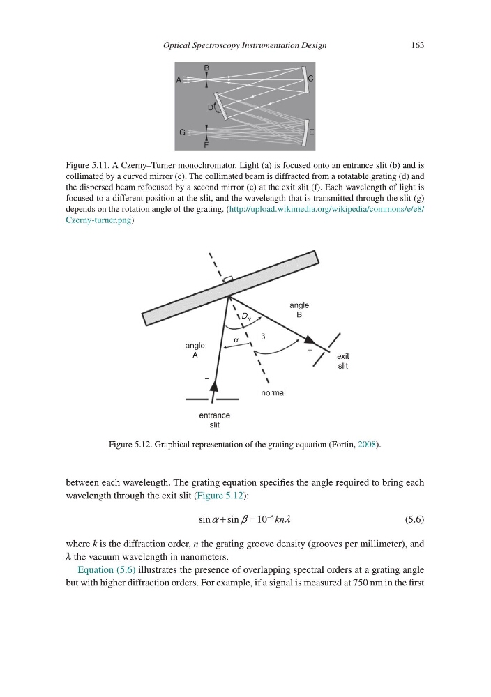
between each wavelength. The grating equation specifies the angle required to bring each
wavelength through the exit slit (Figure 5.12):
sinα
β
λ
+
=
−
sin
10
6
kn
(5.6)
where k is the diffraction order, n the grating groove density (grooves per millimeter), and
λ the vacuum wavelength in nanometers.
Equation (5.6) illustrates the presence of overlapping spectral orders at a grating angle
but with higher diffraction orders. For example, if a signal is measured at 750 nm in the first
A
B
D
G
E
C
F
Figure 5.11. A Czerny–Turner monochromator. Light (a) is focused onto an entrance slit (b) and is
collimated by a curved mirror (c). The collimated beam is diffracted from a rotatable grating (d) and
the dispersed beam refocused by a second mirror (e) at the exit slit (f). Each wavelength of light is
focused to a different position at the slit, and the wavelength that is transmitted through the slit (g)
depends on the rotation angle of the grating. (http://upload.wikimedia.org/wikipedia/commons/e/e8/
Czerny-turner.png)
angle
A
angle
B
normal
D ν
entrance
slit
exit
slit
α
β
+
–
Figure 5.12. Graphical representation of the grating equation (Fortin, 2008).
163
between each wavelength. The grating equation specifies the angle required to bring each
wavelength through the exit slit (Figure 5.12):
sinα
β
λ
+
=
−
sin
10
6
kn
(5.6)
where k is the diffraction order, n the grating groove density (grooves per millimeter), and
λ the vacuum wavelength in nanometers.
Equation (5.6) illustrates the presence of overlapping spectral orders at a grating angle
but with higher diffraction orders. For example, if a signal is measured at 750 nm in the first
A
B
D
G
E
C
F
Figure 5.11. A Czerny–Turner monochromator. Light (a) is focused onto an entrance slit (b) and is
collimated by a curved mirror (c). The collimated beam is diffracted from a rotatable grating (d) and
the dispersed beam refocused by a second mirror (e) at the exit slit (f). Each wavelength of light is
focused to a different position at the slit, and the wavelength that is transmitted through the slit (g)
depends on the rotation angle of the grating. (http://upload.wikimedia.org/wikipedia/commons/e/e8/
Czerny-turner.png)
angle
A
angle
B
normal
D ν
entrance
slit
exit
slit
α
β
+
–
Figure 5.12. Graphical representation of the grating equation (Fortin, 2008).