

58
3.
WAVE—LENGTH OF THE ELECTRON
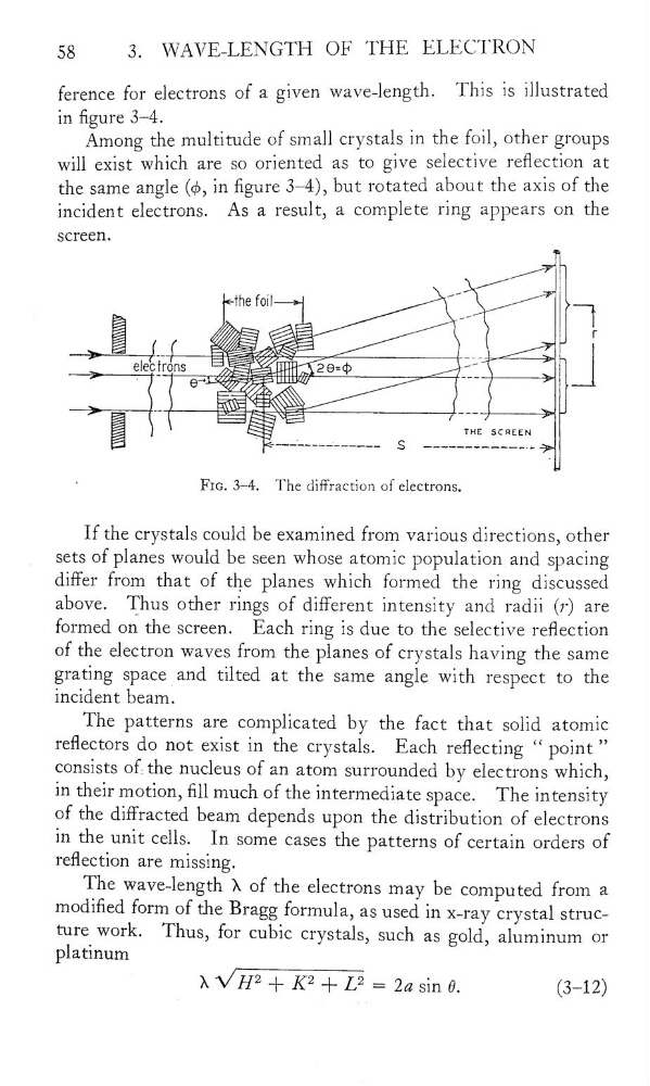
ference for electrons of a given wave-length.
This is illustrated
in figure 3—4.
Among the multitude of small crystals in the forl, other groups
will exist which are so oriented as to give selective reflection at
the same angle (QS, in gure 3—4), but rotated about the axis of the
incident electrons.
As a result, a complete ring appears on the
screen.
ihef0il
.”
—l
_.-_.
-
elecîrons
ÊËÊ—ZlläinM
411
_l
=ËË‘=
THE
SCÊEEN
%
'
--——'______…___
s
__________-_…
‘
FIG. 3—4.
The diffraction of electrons.
If the crystals could be examined from various directions, other
_
sets of planes would be seen whose atomic population and spacing
differ from that of the planes which formed the ring discussed
above.
Thus other rings of different intensity and radii (?“) are
formed on the screen.
Each ring is due to the selective reection
of the electron waves from the planes of crystals having the same
grating space and tilted at the same angle With respect to the
incident beam.
The patterns are complicated by the fact that solid atomic
reectors do not exist in the crystals.
Each reecting
“
point”
consists of the nucleus of an atom surrounded by electrons which,
in their motion, fill much of the intermediate space.
The intensity
of the diffracted beam depends upon the distribution of electrons
in the unit cells.
In some cases the patterns of certain orders of
reection are missing.
The wave—length >\ of the electrons may be computed from &
modied form of the Bragg formula, as used in X—l‘aÿ crystal structure work.
Thus, for cubic crystals, such as gold, aluminum Of
platinum
>. … = 261 sin 9.
(3—12)
3.
WAVE—LENGTH OF THE ELECTRON
ference for electrons of a given wave-length.
This is illustrated
in figure 3—4.
Among the multitude of small crystals in the forl, other groups
will exist which are so oriented as to give selective reflection at
the same angle (QS, in gure 3—4), but rotated about the axis of the
incident electrons.
As a result, a complete ring appears on the
screen.
ihef0il
.”
—l
_.-_.
-
elecîrons
ÊËÊ—ZlläinM
411
_l
=ËË‘=
THE
SCÊEEN
%
'
--——'______…___
s
__________-_…
‘
FIG. 3—4.
The diffraction of electrons.
If the crystals could be examined from various directions, other
_
sets of planes would be seen whose atomic population and spacing
differ from that of the planes which formed the ring discussed
above.
Thus other rings of different intensity and radii (?“) are
formed on the screen.
Each ring is due to the selective reection
of the electron waves from the planes of crystals having the same
grating space and tilted at the same angle With respect to the
incident beam.
The patterns are complicated by the fact that solid atomic
reectors do not exist in the crystals.
Each reecting
“
point”
consists of the nucleus of an atom surrounded by electrons which,
in their motion, fill much of the intermediate space.
The intensity
of the diffracted beam depends upon the distribution of electrons
in the unit cells.
In some cases the patterns of certain orders of
reection are missing.
The wave—length >\ of the electrons may be computed from &
modied form of the Bragg formula, as used in X—l‘aÿ crystal structure work.
Thus, for cubic crystals, such as gold, aluminum Of
platinum
>. … = 261 sin 9.
(3—12)