

448
19.
NOTES ON HIGH VOLTAGE TECHNIQUE
tric.
Instead, a large part of the potential drop occurs near the
inner cylinder, as shown at C in gure 19—6. Thus,
'
dV
V
G —
dx
—
xloge (R/r)
volts/cm.,
(19—2).
where V is the applied potential, G is the eld intensity or gradient
of voltage x centimeters from the axis, R is the inner radius of the
outer cylinder and 7 is the outer radius of the inner cylinder.
In the so—called gradient insulaz‘0m, a material of fairly high
dielectric constant is placed around the inner cylinder, as at D in
'
gure 19—6, in order to lower the electric stress in this region.
This is surrounded With an insulator of lower dielectric constant,
etc.
19—9.
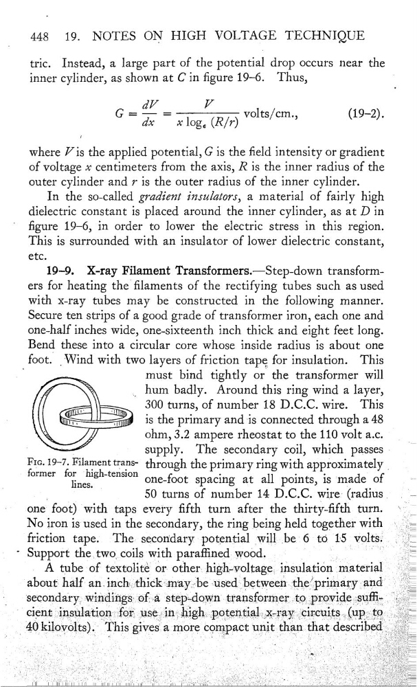
X—ray Fament Transformers.—Step-down transformers for heating thelaments of the rectifying tubes such as used
With X—ray tubes may be constructed in the following manner.
Secure ten strips of a good grade of transformer iron, each one and
one-half inches Wide, one—sixteenth inch thick and eight feet long.
Bend these into a circular core whose inside radins is about one
foot. _Wind With two layers of friction tape for insulation. This
must bind tightly or" the transformer Will
;”
“‘
hum badly. Around this ring wind a layer,
(€Œ5
300 turns, of number 18 D.C.C. wire.
This
—
iluiù‘__,—…wiif is the primary and is connected through a 48
—.___
,/
ohm, 3.2 ampere rheostat to the 110 volt a.c.
_
'
supply. The secondary coil, which passes -
FIG- 19“7-FÏ1afïlent tïa}13' through the primary ring With approximately
_
former
for ‘h1gh—tensmn
-
-
-
.
lines.
one-foot spac1ng
at
all pornts, IS made of
-
_
50 turns of number 14 D.C.C. wire: (radius_
,
one“ foot) With taps every fifth turn after the thirty-fth turn.
\
No iron is used in the secondary, the ring being held together With
friction tape.
The secondary potential will,be 6 to 16 voltS£
-_
'
Support
coilswith parañined WOÔd.
'
“:
A tube of textolitè or other—highwoltage ihsulati0n material
_
‘about half an
widig‘s;
transformer
Ï
‘
€icm: 1nsulatwnfor 1186 m high petentlal xray mreu1ts (upt0
40 kiloïvôlfts) This
unit
described
19.
NOTES ON HIGH VOLTAGE TECHNIQUE
tric.
Instead, a large part of the potential drop occurs near the
inner cylinder, as shown at C in gure 19—6. Thus,
'
dV
V
G —
dx
—
xloge (R/r)
volts/cm.,
(19—2).
where V is the applied potential, G is the eld intensity or gradient
of voltage x centimeters from the axis, R is the inner radius of the
outer cylinder and 7 is the outer radius of the inner cylinder.
In the so—called gradient insulaz‘0m, a material of fairly high
dielectric constant is placed around the inner cylinder, as at D in
'
gure 19—6, in order to lower the electric stress in this region.
This is surrounded With an insulator of lower dielectric constant,
etc.
19—9.
X—ray Fament Transformers.—Step-down transformers for heating thelaments of the rectifying tubes such as used
With X—ray tubes may be constructed in the following manner.
Secure ten strips of a good grade of transformer iron, each one and
one-half inches Wide, one—sixteenth inch thick and eight feet long.
Bend these into a circular core whose inside radins is about one
foot. _Wind With two layers of friction tape for insulation. This
must bind tightly or" the transformer Will
;”
“‘
hum badly. Around this ring wind a layer,
(€Œ5
300 turns, of number 18 D.C.C. wire.
This
—
iluiù‘__,—…wiif is the primary and is connected through a 48
—.___
,/
ohm, 3.2 ampere rheostat to the 110 volt a.c.
_
'
supply. The secondary coil, which passes -
FIG- 19“7-FÏ1afïlent tïa}13' through the primary ring With approximately
_
former
for ‘h1gh—tensmn
-
-
-
.
lines.
one-foot spac1ng
at
all pornts, IS made of
-
_
50 turns of number 14 D.C.C. wire: (radius_
,
one“ foot) With taps every fifth turn after the thirty-fth turn.
\
No iron is used in the secondary, the ring being held together With
friction tape.
The secondary potential will,be 6 to 16 voltS£
-_
'
Support
coilswith parañined WOÔd.
'
“:
A tube of textolitè or other—highwoltage ihsulati0n material
_
‘about half an
widig‘s;
transformer
Ï
‘
€icm: 1nsulatwnfor 1186 m high petentlal xray mreu1ts (upt0
40 kiloïvôlfts) This
unit
described