

370
16.
VACUUM TECHNIQUE
emission, and vice versa.
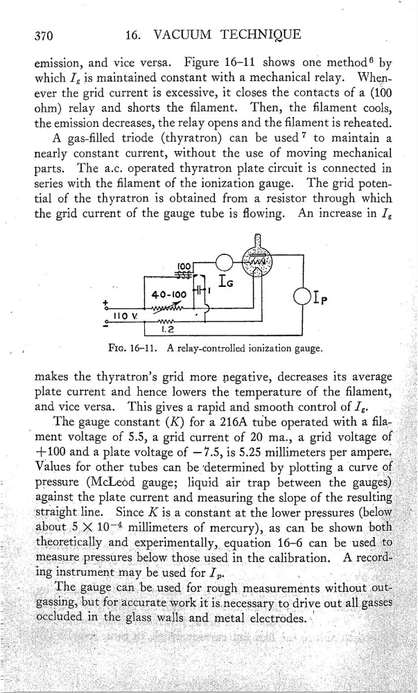
Figure 16—11 shows one method6 by
which lg is maintained constant with a mechanical relay. Whe}ï—
ever the grid current is excessive, it closes the contacts of a (100
ohm‘) relay and shorts the lament. Then, the lament cools,
the emission decreases, the relay opens and the lament is reheated.
A gas—lled triode (thyratron) can be used7 to maintain a
nearly constant current, without the use of moving mechanical
parts.
The a.c. operated thyratron plate circuit is connected in
series with the lament of the ionization gauge.
The grid potential of the thyratron is obtained from a resistor through which
_
the grid current of the gauge tube is owing. An increase in lg
.
°
.
_
IG
.
4°.°°
|
.IP
,
; ?
°
“° v
,
'
Ï,
'
FIG. 16—11.
A relay-controlled ionization gauge.
makes the thyratron’s grid more negative, decreases its average
plate current and hence lowers the temperature
of the lament,
and vice versa.
This gives a rapid and smooth control of lg.
The gauge constant (K) for a 216A tube operated with a la—
voltage of 5.5, a grid Current of 20 ma., a grid voltage of
,
+100
and a plate voltage of —7.5, is 5.25 millimeters per
Values for other tubes can be‘determined by plotting a Curve Of
-
preSsure (McLeèd gauge; liquid air trap between the gauges)
_
against the plate current and measuring the slope of the resulting
Since K isa constant at the lower pressures (below
millimeters
as
can be_ shownb0th
theoœuçally
equation 16—6 can be used’t®
measurepressures below those
in the calibration.
record—
Thegaugecanbeuæd for roughmeasurements Wlth0ut0ut
16.
VACUUM TECHNIQUE
emission, and vice versa.
Figure 16—11 shows one method6 by
which lg is maintained constant with a mechanical relay. Whe}ï—
ever the grid current is excessive, it closes the contacts of a (100
ohm‘) relay and shorts the lament. Then, the lament cools,
the emission decreases, the relay opens and the lament is reheated.
A gas—lled triode (thyratron) can be used7 to maintain a
nearly constant current, without the use of moving mechanical
parts.
The a.c. operated thyratron plate circuit is connected in
series with the lament of the ionization gauge.
The grid potential of the thyratron is obtained from a resistor through which
_
the grid current of the gauge tube is owing. An increase in lg
.
°
.
_
IG
.
4°.°°
|
.IP
,
; ?
°
“° v
,
'
Ï,
'
FIG. 16—11.
A relay-controlled ionization gauge.
makes the thyratron’s grid more negative, decreases its average
plate current and hence lowers the temperature
of the lament,
and vice versa.
This gives a rapid and smooth control of lg.
The gauge constant (K) for a 216A tube operated with a la—
voltage of 5.5, a grid Current of 20 ma., a grid voltage of
,
+100
and a plate voltage of —7.5, is 5.25 millimeters per
Values for other tubes can be‘determined by plotting a Curve Of
-
preSsure (McLeèd gauge; liquid air trap between the gauges)
_
against the plate current and measuring the slope of the resulting
Since K isa constant at the lower pressures (below
millimeters
as
can be_ shownb0th
theoœuçally
equation 16—6 can be used’t®
measurepressures below those
in the calibration.
record—
Thegaugecanbeuæd for roughmeasurements Wlth0ut0ut