

13—3.
RECTIFIERS
297
13—3.
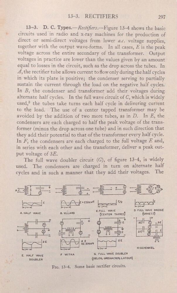
D. C. Types.—Rectiem.—Figure 13—4 shows the basic
"
circuits
radio and x—ray machines for the production of
'
direct or semi-direct voltages from lower a.c. voltage supplies,
together with the output wave—forms. In all cases, E is the peak
voltage across the entire secondary of the transformer. Output
voltages in practice are lower than the values given by an amount
equal to losses in the circuit, such as the drop across the tubes… In
Â, the rectiertube allows current to flow only during the half cycles
in which its plate is positive; the condenser serving to partially
_
sustain the current through the load on the negative half cycles.
_
_
In B, the condenser and transformer add their voltages during
alternate half cycles. In the full wave circuit of C, which is widely
used,3 the tubes take turns each half cycle in delivering current
‘
to the load.
The use of a center tapped transformer may be
avoided by the addition of two more tubes, as in D. In E, the
_
condensers are each charged to half the peak voltage of the trans—
former (minus the drop across one tube) and in such direction that
they add their potential to that of the transformer every half cycle.
In F, the condensers are each charged to the full‘voltage E and,
'
series With each other and the transformer,deliver a peak out_
_
put voltage of 3E.
.
_
The full wave doubler circuit (G), of gure
is widely
_
used.
The condensers are charged in turn on alternate half
.
cycles and in such a manner that they add their voltages. The
@mŒE t SlËË Sl- ral.»
€
€
_'
-
-
E
È-—-——-Ï---js
|
_
l
/2
'
C.FULL
WAVE
D.-FULL WAVE BRIDGE
‘
A. HALF WAVE
a. VILLARD
(«CENTER TAPPED)
(GRAETZ)
+
'
+ E+
-
.4E
+
3EË
=
-
.
_
m
_
I‘]
+
-
-
-
---_
__
ze
Î:Êmwc
25
_
w
’
_
…
-
…
H:SCHENKEL'
HALF
WAVE
’
r “WITKA
_a FULL WAVE DOUBLER
_
_
"
.'
'
DOUBLER
.
,
_(DEL0N,GRE…ACKER,LAT9U).
__
_
—
FIG. 13—4'.
Some basic rectier circuits.
__
'
_
RECTIFIERS
297
13—3.
D. C. Types.—Rectiem.—Figure 13—4 shows the basic
"
circuits
radio and x—ray machines for the production of
'
direct or semi-direct voltages from lower a.c. voltage supplies,
together with the output wave—forms. In all cases, E is the peak
voltage across the entire secondary of the transformer. Output
voltages in practice are lower than the values given by an amount
equal to losses in the circuit, such as the drop across the tubes… In
Â, the rectiertube allows current to flow only during the half cycles
in which its plate is positive; the condenser serving to partially
_
sustain the current through the load on the negative half cycles.
_
_
In B, the condenser and transformer add their voltages during
alternate half cycles. In the full wave circuit of C, which is widely
used,3 the tubes take turns each half cycle in delivering current
‘
to the load.
The use of a center tapped transformer may be
avoided by the addition of two more tubes, as in D. In E, the
_
condensers are each charged to half the peak voltage of the trans—
former (minus the drop across one tube) and in such direction that
they add their potential to that of the transformer every half cycle.
In F, the condensers are each charged to the full‘voltage E and,
'
series With each other and the transformer,deliver a peak out_
_
put voltage of 3E.
.
_
The full wave doubler circuit (G), of gure
is widely
_
used.
The condensers are charged in turn on alternate half
.
cycles and in such a manner that they add their voltages. The
@mŒE t SlËË Sl- ral.»
€
€
_'
-
-
E
È-—-——-Ï---js
|
_
l
/2
'
C.FULL
WAVE
D.-FULL WAVE BRIDGE
‘
A. HALF WAVE
a. VILLARD
(«CENTER TAPPED)
(GRAETZ)
+
'
+ E+
-
.4E
+
3EË
=
-
.
_
m
_
I‘]
+
-
-
-
---_
__
ze
Î:Êmwc
25
_
w
’
_
…
-
…
H:SCHENKEL'
HALF
WAVE
’
r “WITKA
_a FULL WAVE DOUBLER
_
_
"
.'
'
DOUBLER
.
,
_(DEL0N,GRE…ACKER,LAT9U).
__
_
—
FIG. 13—4'.
Some basic rectier circuits.
__
'
_