

6—5.
THE PLATE RESISTANCE r,,
121
Equations for ,u have been derived from equations for C12 and
C13 and used in the design of triodes.4 It is found, both theoretically and experimentally, that ,a is greater when the grid-lament
distance is much less than the grid-plate distance and when the
grid is made of large wires, close together. ln some tubes, called
variable mu 07" super control-tubes, the grid is constructed with the
wires close together near its ends and with considerably greater
spacing in its middle. The result is that the lower left end of the
characteristic curves approach the grid-voltage axis much more
slowly and only reach it at a large negative grid potential. Tubes
with a ”sharp cut-of” have great uniformity in the spacing of the
grid wires and in axial symmetry with the lament and plate.
6—5.
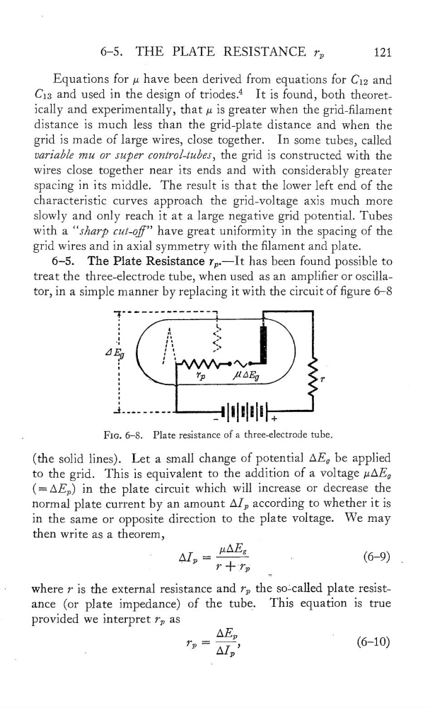
The Plate Resistance r,,.——It has been found possible to
treat the three—electrode tube, when used as an amplier or oscilla—
tor, in a simple manner by replacing it With the circuit of gure 6—8
"f""""‘“"""
,
:
"*
<Ë:
AÊg
;
Tp
/1AEg
T
-
mum .
.
FIG. 6—8.
Plate resistance of a three—electrode tube.
(the solid lines). Let a small change of potential
be applied
to the grid. This is equivalent to the addition of a voltage pAEa
(=AEp) in the plate circuit which Will increase or decrease the
normal plate current by an amount Al,, according to whether it is
in the same or opposite direction to the plate voltage. We may
then write as a theorem,
NAEg
Alp —
r+—_r,,
(6 9)
_
—
Where 7 is the external resistance and r,, the soècalled plate resist—
ance
(or plate impedance) of the tube.
This equation is true
provided we interpret r,, as
AE,,
,
r,, —
AI,,’
(6 10)
THE PLATE RESISTANCE r,,
121
Equations for ,u have been derived from equations for C12 and
C13 and used in the design of triodes.4 It is found, both theoretically and experimentally, that ,a is greater when the grid-lament
distance is much less than the grid-plate distance and when the
grid is made of large wires, close together. ln some tubes, called
variable mu 07" super control-tubes, the grid is constructed with the
wires close together near its ends and with considerably greater
spacing in its middle. The result is that the lower left end of the
characteristic curves approach the grid-voltage axis much more
slowly and only reach it at a large negative grid potential. Tubes
with a ”sharp cut-of” have great uniformity in the spacing of the
grid wires and in axial symmetry with the lament and plate.
6—5.
The Plate Resistance r,,.——It has been found possible to
treat the three—electrode tube, when used as an amplier or oscilla—
tor, in a simple manner by replacing it With the circuit of gure 6—8
"f""""‘“"""
,
:
"*
<Ë:
AÊg
;
Tp
/1AEg
T
-
mum .
.
FIG. 6—8.
Plate resistance of a three—electrode tube.
(the solid lines). Let a small change of potential
be applied
to the grid. This is equivalent to the addition of a voltage pAEa
(=AEp) in the plate circuit which Will increase or decrease the
normal plate current by an amount Al,, according to whether it is
in the same or opposite direction to the plate voltage. We may
then write as a theorem,
NAEg
Alp —
r+—_r,,
(6 9)
_
—
Where 7 is the external resistance and r,, the soècalled plate resist—
ance
(or plate impedance) of the tube.
This equation is true
provided we interpret r,, as
AE,,
,
r,, —
AI,,’
(6 10)