

52
own channel. The setting of these fractions is often critically dependant upon the gain setting
for the various fluorescent channels. Thus small setting in photomultiplier high voltage or
amplifier gains can result in large changes in the necessary compensation.
The proper sequence for setting compensation is first to run the "negative" sample, placing
it in the desired position by adjusting gain in all fluorescence channels. Next the brightest
possible sample of each fluorochrome is run, and gains are further adjusted so that these are
on scale. Having thus established the required gain settings to visualize both the dimmest and
the brightest samples, these setting are fixed and must not be changed during compensation.
Then, bright examples of each fluorochrome alone are run sequentially and adjusted so that
the mean fluorescence signal obtained in the non-relevant fluorescence channels is the same
as the mean for the negative control in that channel. The result is that each fluorochrome
gives a signal only in its appropriate channel.
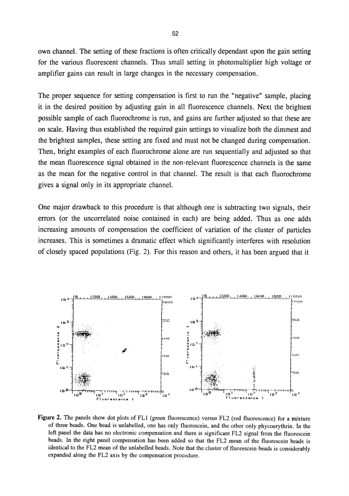
One major drawback to this procedure is that although one is subtracting two signals, their
errors (or the uncorrelated noise contained in each) are being added. Thus as one adds
increasing amounts of compensation the coefficient of variation of the cluster of particles
increases. This is sometimes a dramatic effect which significantly interferes with resolution
of closely spaced populations (Fig. 2). For this reason and others, it has been argued that it
Figure 2. The panels show dot plots of FLl (green fluorescence) versus FL2 (red fluorescence) for a mixture
of three beads. One bead is unlabelled, one has only fluorescein, and the other only phycoerythrin. In the
left panel the data has no electronic compensation and there is significant FL2 signal from the fluorescein
beads. In the right panel compensation has been added so that the FL2 mean of the fluorescein beads is
identical to the FL2 mean of the unlabelled beads. Note that the cluster of fluorescein beads is considerably
expanded along the FL2 axis by the compensation procedure.
own channel. The setting of these fractions is often critically dependant upon the gain setting
for the various fluorescent channels. Thus small setting in photomultiplier high voltage or
amplifier gains can result in large changes in the necessary compensation.
The proper sequence for setting compensation is first to run the "negative" sample, placing
it in the desired position by adjusting gain in all fluorescence channels. Next the brightest
possible sample of each fluorochrome is run, and gains are further adjusted so that these are
on scale. Having thus established the required gain settings to visualize both the dimmest and
the brightest samples, these setting are fixed and must not be changed during compensation.
Then, bright examples of each fluorochrome alone are run sequentially and adjusted so that
the mean fluorescence signal obtained in the non-relevant fluorescence channels is the same
as the mean for the negative control in that channel. The result is that each fluorochrome
gives a signal only in its appropriate channel.
One major drawback to this procedure is that although one is subtracting two signals, their
errors (or the uncorrelated noise contained in each) are being added. Thus as one adds
increasing amounts of compensation the coefficient of variation of the cluster of particles
increases. This is sometimes a dramatic effect which significantly interferes with resolution
of closely spaced populations (Fig. 2). For this reason and others, it has been argued that it
Figure 2. The panels show dot plots of FLl (green fluorescence) versus FL2 (red fluorescence) for a mixture
of three beads. One bead is unlabelled, one has only fluorescein, and the other only phycoerythrin. In the
left panel the data has no electronic compensation and there is significant FL2 signal from the fluorescein
beads. In the right panel compensation has been added so that the FL2 mean of the fluorescein beads is
identical to the FL2 mean of the unlabelled beads. Note that the cluster of fluorescein beads is considerably
expanded along the FL2 axis by the compensation procedure.