

6.3 Technical Parameters of the Automated One-Channel
IR-Radiometer
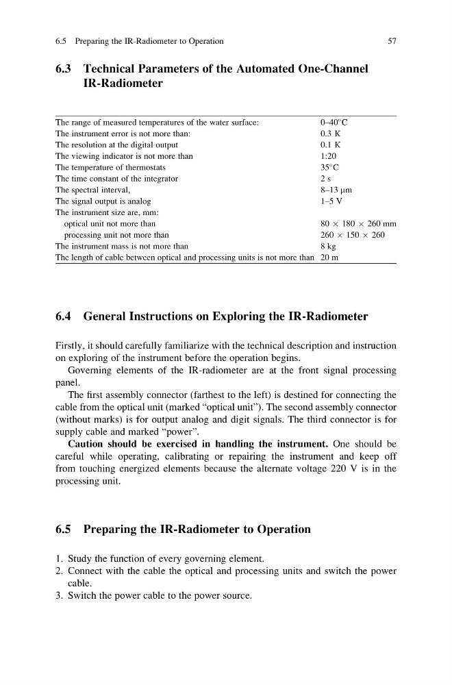
The range of measured temperatures of the water surface:
0–40
C
The instrument error is not more than:
0.3 К
The resolution at the digital output
0.1 К
The viewing indicator is not more than
1:20
The temperature of thermostats
35
C
The time constant of the integrator
2 s
The spectral interval,
8–13 mm
The signal output is analog
1–5 V
The instrument size are, mm:
optical unit not more than
80 Â 180 Â 260 mm
processing unit not more than
260 Â 150 Â 260
The instrument mass is not more than
8 kg
The length of cable between optical and processing units is not more than 20 m
6.4 General Instructions on Exploring the IR-Radiometer
Firstly, it should carefully familiarize with the technical description and instruction
on exploring of the instrument before the operation begins.
Governing elements of the IR-radiometer are at the front signal processing
panel.
The first assembly connector (farthest to the left) is destined for connecting the
cable from the optical unit (marked “optical unit”). The second assembly connector
(without marks) is for output analog and digit signals. The third connector is for
supply cable and marked “power”.
Caution should be exercised in handling the instrument. One should be
careful while operating, calibrating or repairing the instrument and keep off
from touching energized elements because the alternate voltage 220 V is in the
processing unit.
6.5 Preparing the IR-Radiometer to Operation
1. Study the function of every governing element.
2. Connect with the cable the optical and processing units and switch the power
cable.
3. Switch the power cable to the power source.
6.5 Preparing the IR-Radiometer to Operation
57
IR-Radiometer
The range of measured temperatures of the water surface:
0–40
C
The instrument error is not more than:
0.3 К
The resolution at the digital output
0.1 К
The viewing indicator is not more than
1:20
The temperature of thermostats
35
C
The time constant of the integrator
2 s
The spectral interval,
8–13 mm
The signal output is analog
1–5 V
The instrument size are, mm:
optical unit not more than
80 Â 180 Â 260 mm
processing unit not more than
260 Â 150 Â 260
The instrument mass is not more than
8 kg
The length of cable between optical and processing units is not more than 20 m
6.4 General Instructions on Exploring the IR-Radiometer
Firstly, it should carefully familiarize with the technical description and instruction
on exploring of the instrument before the operation begins.
Governing elements of the IR-radiometer are at the front signal processing
panel.
The first assembly connector (farthest to the left) is destined for connecting the
cable from the optical unit (marked “optical unit”). The second assembly connector
(without marks) is for output analog and digit signals. The third connector is for
supply cable and marked “power”.
Caution should be exercised in handling the instrument. One should be
careful while operating, calibrating or repairing the instrument and keep off
from touching energized elements because the alternate voltage 220 V is in the
processing unit.
6.5 Preparing the IR-Radiometer to Operation
1. Study the function of every governing element.
2. Connect with the cable the optical and processing units and switch the power
cable.
3. Switch the power cable to the power source.
6.5 Preparing the IR-Radiometer to Operation
57