

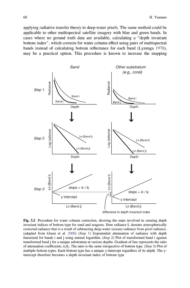
applying radiative transfer theory to deep-water pixels. The same method could be
applicable to other multispectral satellite imagery with blue and green bands. In
cases where no ground truth data are available, calculating a ‘‘depth invariant
bottom index’’, which corrects for water column effect using pairs of multispectral
bands instead of calculating bottom reflectance for each band (Lyzenga 1978),
may be a practical option. This procedure is known to increase the mapping
Radiance
Depth
Radiance
Depth
Log radiance
Depth
Ln (Band i)
Ln (Band j)
Log radiance
Depth
Ln (Band i)
Ln (Band j)
Ln (Band i)
Ln (Band j)
slope = ki / kj
y intercept
Ln (Band i)
Ln (Band j)
slope = ki / kj
y intercept
difference in depth invariant index
Sand
Other substratum
(e.g., coral)
Band i
Band j
Band i
Band j
Step 1
Step 2
Step 3
Fig. 3.2 Procedure for water column correction, showing the steps involved in creating depth
invariant indices of bottom type for sand and seagrass. Here radiance L denotes atmospherically
corrected radiance that is a result of subtracting deep-water (ocean) radiance from pixel radiance.
(adapted from Green et al. 2000) (Step 1) Exponential attenuation of radiance with depth
linearized for bands i and j using natural logarithm. (Step 2) Plot of transformed band i against
transformed band j for a unique substratum at various depths. Gradient of line represents the ratio
of attenuation coefficients, k i /k j . The ratio is the same irrespective of bottom type. (Step 3) Plot of
multiple bottom types. Each bottom type has a unique y-intercept regardless of its depth. The yintercept therefore becomes a depth invariant index of bottom type
60
H. Yamano
applicable to other multispectral satellite imagery with blue and green bands. In
cases where no ground truth data are available, calculating a ‘‘depth invariant
bottom index’’, which corrects for water column effect using pairs of multispectral
bands instead of calculating bottom reflectance for each band (Lyzenga 1978),
may be a practical option. This procedure is known to increase the mapping
Radiance
Depth
Radiance
Depth
Log radiance
Depth
Ln (Band i)
Ln (Band j)
Log radiance
Depth
Ln (Band i)
Ln (Band j)
Ln (Band i)
Ln (Band j)
slope = ki / kj
y intercept
Ln (Band i)
Ln (Band j)
slope = ki / kj
y intercept
difference in depth invariant index
Sand
Other substratum
(e.g., coral)
Band i
Band j
Band i
Band j
Step 1
Step 2
Step 3
Fig. 3.2 Procedure for water column correction, showing the steps involved in creating depth
invariant indices of bottom type for sand and seagrass. Here radiance L denotes atmospherically
corrected radiance that is a result of subtracting deep-water (ocean) radiance from pixel radiance.
(adapted from Green et al. 2000) (Step 1) Exponential attenuation of radiance with depth
linearized for bands i and j using natural logarithm. (Step 2) Plot of transformed band i against
transformed band j for a unique substratum at various depths. Gradient of line represents the ratio
of attenuation coefficients, k i /k j . The ratio is the same irrespective of bottom type. (Step 3) Plot of
multiple bottom types. Each bottom type has a unique y-intercept regardless of its depth. The yintercept therefore becomes a depth invariant index of bottom type
60
H. Yamano