

164
Paola Podest` a, Barbara Catania, and Alberto Belussi
distance is used to evaluate similarity of spatial scenes, by taking into account also
direction and distance relations. In [11], topology distance is used to define a model
(snapshot model) to compare two different topological relations between lines and
regions. In all the papers cited above, similarity is computed only between pairs of
objects with the same dimension. Multiple object representations are not considered
at all.
Two different consistency issues are addressed in [18, 19]. In [18], consistency
among networks, defined as sets of lines (homogeneous networks) and sets of lines
and regions (heterogeneous networks), is investigated. In [19], the problem of checking consistency under aggregation operations, that merge together disconnected parts
of the same region, is considered. Both approaches do not consider changes in object
dimension and no similarity measure is provided.
8.2.2 Cardinal Directional Relationships
Cardinal directional relations provide a way to determine what is the relative position
of a target object with respect to a reference object by considering some cardinal
directions.
The idea behind a qualitative representation of cardinal relations is to map quantitative directional information (i.e. the degrees of an angle) into a set of symbols.
More precisely, directional relationships are binary functions that map two object
points (P1, P2) in the plane (representing respectively the reference object used to define directions and the target object whose direction with respect to the reference object has to be detected) onto a symbolic direction d. The number of direction symbols
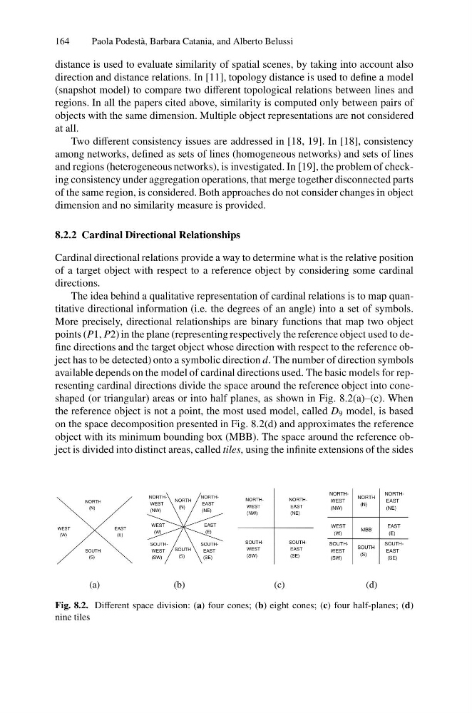
available depends on the model of cardinal directions used. The basic models for representing cardinal directions divide the space around the reference object into coneshaped (or triangular) areas or into half planes, as shown in Fig. 8.2(a)–(c). When
the reference object is not a point, the most used model, called D 9 model, is based
on the space decomposition presented in Fig. 8.2(d) and approximates the reference
object with its minimum bounding box (MBB). The space around the reference object is divided into distinct areas, called tiles, using the infinite extensions of the sides
EAST
(E)
NORTH
(N)
WEST
(W)
SOUTH
(S)
EAST
(E)
NORTHWEST
(NW)
WEST
(W)
SOUTH
(S)
NORTHEAST
(NE)
NORTH
(N)
SOUTHEAST
(SE)
SOUTHWEST
(SW)
NORTHEAST
(NE)
NORTHWEST
(NW)
SOUTHEAST
(SE)
SOUTHWEST
(SW)
NORTHEAST
(NE)
NORTHWEST
(NW)
SOUTHEAST
(SE)
SOUTHWEST
(SW)
NORTH
(N)
SOUTH
(S)
MBB
EAST
(E)
WEST
(W)
(a)
(b)
(c)
(d)
Fig. 8.2. Different space division: (a) four cones; (b) eight cones; (c) four half-planes; (d)
nine tiles
Paola Podest` a, Barbara Catania, and Alberto Belussi
distance is used to evaluate similarity of spatial scenes, by taking into account also
direction and distance relations. In [11], topology distance is used to define a model
(snapshot model) to compare two different topological relations between lines and
regions. In all the papers cited above, similarity is computed only between pairs of
objects with the same dimension. Multiple object representations are not considered
at all.
Two different consistency issues are addressed in [18, 19]. In [18], consistency
among networks, defined as sets of lines (homogeneous networks) and sets of lines
and regions (heterogeneous networks), is investigated. In [19], the problem of checking consistency under aggregation operations, that merge together disconnected parts
of the same region, is considered. Both approaches do not consider changes in object
dimension and no similarity measure is provided.
8.2.2 Cardinal Directional Relationships
Cardinal directional relations provide a way to determine what is the relative position
of a target object with respect to a reference object by considering some cardinal
directions.
The idea behind a qualitative representation of cardinal relations is to map quantitative directional information (i.e. the degrees of an angle) into a set of symbols.
More precisely, directional relationships are binary functions that map two object
points (P1, P2) in the plane (representing respectively the reference object used to define directions and the target object whose direction with respect to the reference object has to be detected) onto a symbolic direction d. The number of direction symbols
available depends on the model of cardinal directions used. The basic models for representing cardinal directions divide the space around the reference object into coneshaped (or triangular) areas or into half planes, as shown in Fig. 8.2(a)–(c). When
the reference object is not a point, the most used model, called D 9 model, is based
on the space decomposition presented in Fig. 8.2(d) and approximates the reference
object with its minimum bounding box (MBB). The space around the reference object is divided into distinct areas, called tiles, using the infinite extensions of the sides
EAST
(E)
NORTH
(N)
WEST
(W)
SOUTH
(S)
EAST
(E)
NORTHWEST
(NW)
WEST
(W)
SOUTH
(S)
NORTHEAST
(NE)
NORTH
(N)
SOUTHEAST
(SE)
SOUTHWEST
(SW)
NORTHEAST
(NE)
NORTHWEST
(NW)
SOUTHEAST
(SE)
SOUTHWEST
(SW)
NORTHEAST
(NE)
NORTHWEST
(NW)
SOUTHEAST
(SE)
SOUTHWEST
(SW)
NORTH
(N)
SOUTH
(S)
MBB
EAST
(E)
WEST
(W)
(a)
(b)
(c)
(d)
Fig. 8.2. Different space division: (a) four cones; (b) eight cones; (c) four half-planes; (d)
nine tiles