

sludge Y
water
water
.,..-.,.,j,"""'",....,...-+water
-----llllll----t---b..l
Anaerobic Wastewater Treatment
Ordinary settling
Gas stripping
+
lamella sedimentation
Refrigeration
+
settling
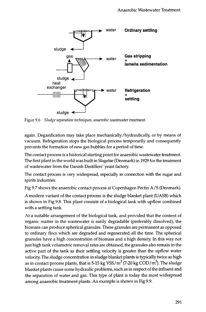
Figur 9.6 Sludge separation techniques, anaerobic wastewater treatment.
again. Degasification may take place mechanically /hydraulically, or by means of
vacuum. Refrigeration stops the biological process temporarily and consequently
prevents the formation of new gas bubbles for a period of time.
The contact process is a historical starting point for anaerobic wastewater treatment.
The first plant in the world was built in Slagelse (Denmark) in 1929 for the treatment
of wastewater from the Danish Destillers' yeast factory.
The contact process is very widespread, especially in connection with the sugar and
spirits industries.
Fig 9.7 shows the anaerobic contact process at Copenhagen Pectin A/S (Denmark).
A modern variant of the contact process is the sludge blanket plant (UASB) which
is shown in Fig 9.8. This plant consists of a biological tank with upflow combined
with a settling tank.
At a suitable arrangement of the biological tank, and provided that the content of
organic matter in the wastewater is easily degradable (preferably dissolved), the
biomass can produce spherical granules. These granules are permanent as opposed
to ordinary floes which are degraded and regenerated all the time. The spherical
granules have a high concentration of biomass and a high density. In this way not
just high tank volumetric removal rates are obtained, the granules also remain in the
active part of the tank as their settling velocity is greater than the upflow water
velocity. The sludge concentration in sludge blanket plants is typically twice as high
as in contact process plants, that is 5-15 kg VSS/m 3 (7-20 kg COD /m~. The sludge
blanket plants cause some hydraulic problems, such as in respect of the influent and
the separation of water and gas. This type of plant is today the most widespread
among anaerobic treatment plants. An example is shown in Fig 9.9.
291
water
water
.,..-.,.,j,"""'",....,...-+water
-----llllll----t---b..l
Anaerobic Wastewater Treatment
Ordinary settling
Gas stripping
+
lamella sedimentation
Refrigeration
+
settling
Figur 9.6 Sludge separation techniques, anaerobic wastewater treatment.
again. Degasification may take place mechanically /hydraulically, or by means of
vacuum. Refrigeration stops the biological process temporarily and consequently
prevents the formation of new gas bubbles for a period of time.
The contact process is a historical starting point for anaerobic wastewater treatment.
The first plant in the world was built in Slagelse (Denmark) in 1929 for the treatment
of wastewater from the Danish Destillers' yeast factory.
The contact process is very widespread, especially in connection with the sugar and
spirits industries.
Fig 9.7 shows the anaerobic contact process at Copenhagen Pectin A/S (Denmark).
A modern variant of the contact process is the sludge blanket plant (UASB) which
is shown in Fig 9.8. This plant consists of a biological tank with upflow combined
with a settling tank.
At a suitable arrangement of the biological tank, and provided that the content of
organic matter in the wastewater is easily degradable (preferably dissolved), the
biomass can produce spherical granules. These granules are permanent as opposed
to ordinary floes which are degraded and regenerated all the time. The spherical
granules have a high concentration of biomass and a high density. In this way not
just high tank volumetric removal rates are obtained, the granules also remain in the
active part of the tank as their settling velocity is greater than the upflow water
velocity. The sludge concentration in sludge blanket plants is typically twice as high
as in contact process plants, that is 5-15 kg VSS/m 3 (7-20 kg COD /m~. The sludge
blanket plants cause some hydraulic problems, such as in respect of the influent and
the separation of water and gas. This type of plant is today the most widespread
among anaerobic treatment plants. An example is shown in Fig 9.9.
291