

Treatment Plants for Denitrification
Filtersurface
om depth
2
3
4
10
\
: - - N 2 -concentration
\ :
in the bulk liquid
\ : · · · · · ~o; -N con~en_tration
- - - -. ·
1n the bulk hqwd
l· - - Saturation concentration
for N 2 in downflow filter
20
30
40
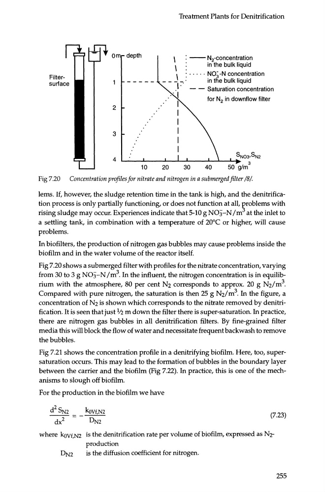
Fig 7.20 Concentration profiles for nitrate and nitrogen in a submerged filter /8/
lems. If, however, the sludge retention time in the tank is high, and the denitrification process is only partially functioning, or does not function at all, ~roblems with
rising sludge may occur. Experiences indicate that 5-10 g N03-N /m at the inlet to
a settling tank, in combination with a temperature of 20°C or higher, will cause
problems.
In biofilters, the production of nitrogen gas bubbles may cause problems inside the
biofilm and in the water volume of the reactor itself.
Fig 7.20 shows a submerged filter with profiles for the nitrate concentration, varying
from 30 to 3 g N03-N /m 3 . In the influent, the nitrogen concentration is in equilibrium with the atmosphere, 80 per cent Nz corresponds to approx. 20 g Nz/m 3 .
Compared with pure nitrogen, the saturation is then 25 g Nz/m 3 . In the figure, a
concentration of Nz is shown which corresponds to the nitrate removed by denitrification. It is seen that just 1 ..-2 m down the filter there is super-saturation. In practice,
there are nitrogen gas bubbles in all denitrification filters. By fine-grained filter
media this will block the flow of water and necessitate frequent backwash to remove
the bubbles.
Fig 7.21 shows the concentration profile in a denitrifying biofilm. Here, too, supersaturation occurs. This may lead to the formation of bubbles in the boundary layer
between the carrier and the biofilm (Fig 7.22). In practice, this is one of the mechanisms to slough off biofilm.
For the production in the biofilm we have
d 2 SN2
kov£,N2
~=- DN2
(7.23)
where kovf,N2 is the denitrification rate per volume of biofilm, expressed as Nzproduction
DN2
is the diffusion coefficient for nitrogen.
255
Filtersurface
om depth
2
3
4
10
\
: - - N 2 -concentration
\ :
in the bulk liquid
\ : · · · · · ~o; -N con~en_tration
- - - -. ·
1n the bulk hqwd
l· - - Saturation concentration
for N 2 in downflow filter
20
30
40
Fig 7.20 Concentration profiles for nitrate and nitrogen in a submerged filter /8/
lems. If, however, the sludge retention time in the tank is high, and the denitrification process is only partially functioning, or does not function at all, ~roblems with
rising sludge may occur. Experiences indicate that 5-10 g N03-N /m at the inlet to
a settling tank, in combination with a temperature of 20°C or higher, will cause
problems.
In biofilters, the production of nitrogen gas bubbles may cause problems inside the
biofilm and in the water volume of the reactor itself.
Fig 7.20 shows a submerged filter with profiles for the nitrate concentration, varying
from 30 to 3 g N03-N /m 3 . In the influent, the nitrogen concentration is in equilibrium with the atmosphere, 80 per cent Nz corresponds to approx. 20 g Nz/m 3 .
Compared with pure nitrogen, the saturation is then 25 g Nz/m 3 . In the figure, a
concentration of Nz is shown which corresponds to the nitrate removed by denitrification. It is seen that just 1 ..-2 m down the filter there is super-saturation. In practice,
there are nitrogen gas bubbles in all denitrification filters. By fine-grained filter
media this will block the flow of water and necessitate frequent backwash to remove
the bubbles.
Fig 7.21 shows the concentration profile in a denitrifying biofilm. Here, too, supersaturation occurs. This may lead to the formation of bubbles in the boundary layer
between the carrier and the biofilm (Fig 7.22). In practice, this is one of the mechanisms to slough off biofilm.
For the production in the biofilm we have
d 2 SN2
kov£,N2
~=- DN2
(7.23)
where kovf,N2 is the denitrification rate per volume of biofilm, expressed as Nzproduction
DN2
is the diffusion coefficient for nitrogen.
255