

Types of plants for nitrification
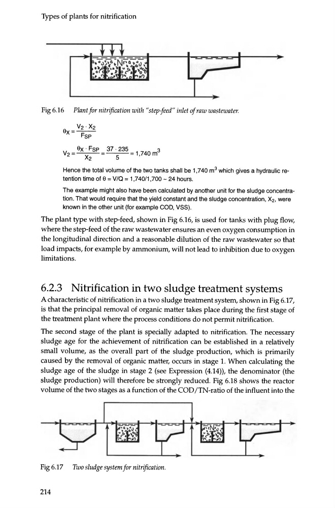
Fig 6.16 Plant for nitrification with "step1eed" inlet of raw wastewater.
V2 · x2
Bx=-Fsp
v 2 = Bx · Fsp = 37 · 235 = 1 740 m3
x2
5
•
Hence the total volume of the two tanks shall be 1, 7 40 m 3 which gives a hydraulic retention time of 9 = V/Q = 1,740/1 ,700- 24 hours.
The example might also have been calculated by another unit for the sludge concentration. That would require that the yield constant and the sludge concentration, X2, were
known in the other unit (for example COD, VSS).
The plant type with step-feed, shown in Fig 6.16, is used for tanks with plug flow,
where the step-feed of the raw wastewater ensures an even oxygen consumption in
the longitudinal direction and a reasonable dilution of the raw wastewater so that
load impacts, for example by ammonium, will not lead to inhibition due to oxygen
limitations.
6.2.3 Nitrification in two sludge treatment systems
A characteristic of nitrification in a two sludge treatment system, shown in Fig 6.17,
is that the principal removal of organic matter takes place during the first stage of
the treatment plant where the process conditions do not permit nitrification.
The second stage of the plant is specially adapted to nitrification. The necessary
sludge age for the achievement of nitrification can be established in a relatively
small volume, as the overall part of the sludge production, which is primarily
caused by the removal of organic matter, occurs in stage 1. When calculating the
sludge age of the sludge in stage 2 (see Expression (4.14)), the denominator (the
sludge production) will therefore be strongly reduced. Fig 6.18 shows the reactor
volume of the two stages as a function of the COD /TN-ratio of the influent into the
Fig 6.17 Two sludge system for nitrification.
214
Fig 6.16 Plant for nitrification with "step1eed" inlet of raw wastewater.
V2 · x2
Bx=-Fsp
v 2 = Bx · Fsp = 37 · 235 = 1 740 m3
x2
5
•
Hence the total volume of the two tanks shall be 1, 7 40 m 3 which gives a hydraulic retention time of 9 = V/Q = 1,740/1 ,700- 24 hours.
The example might also have been calculated by another unit for the sludge concentration. That would require that the yield constant and the sludge concentration, X2, were
known in the other unit (for example COD, VSS).
The plant type with step-feed, shown in Fig 6.16, is used for tanks with plug flow,
where the step-feed of the raw wastewater ensures an even oxygen consumption in
the longitudinal direction and a reasonable dilution of the raw wastewater so that
load impacts, for example by ammonium, will not lead to inhibition due to oxygen
limitations.
6.2.3 Nitrification in two sludge treatment systems
A characteristic of nitrification in a two sludge treatment system, shown in Fig 6.17,
is that the principal removal of organic matter takes place during the first stage of
the treatment plant where the process conditions do not permit nitrification.
The second stage of the plant is specially adapted to nitrification. The necessary
sludge age for the achievement of nitrification can be established in a relatively
small volume, as the overall part of the sludge production, which is primarily
caused by the removal of organic matter, occurs in stage 1. When calculating the
sludge age of the sludge in stage 2 (see Expression (4.14)), the denominator (the
sludge production) will therefore be strongly reduced. Fig 6.18 shows the reactor
volume of the two stages as a function of the COD /TN-ratio of the influent into the
Fig 6.17 Two sludge system for nitrification.
214