

Types of plants, activated sludge plants
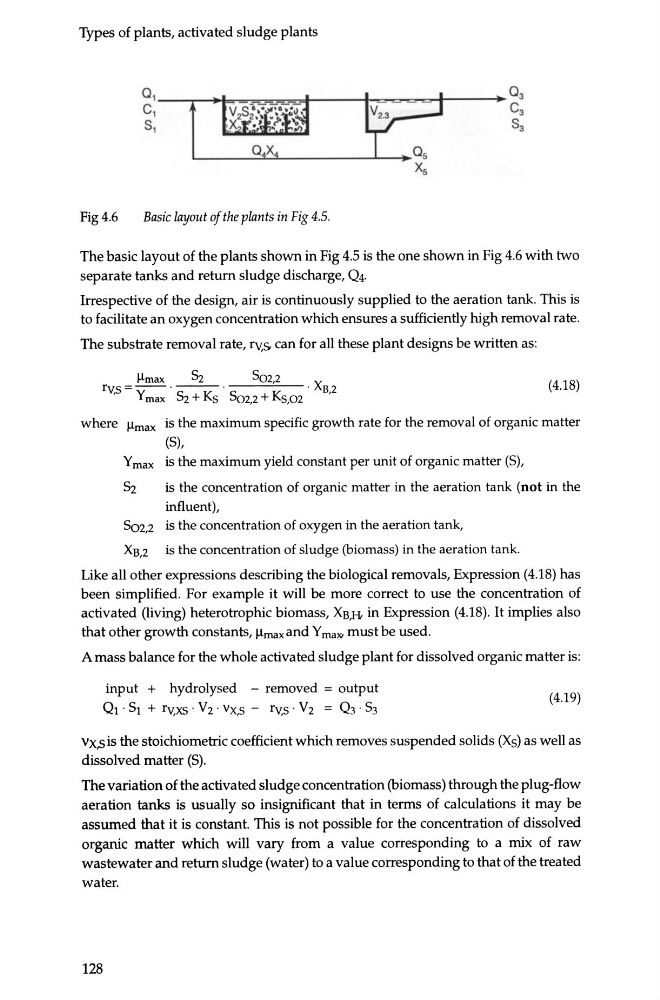
Fig4.6
Basic layout of the plants in Fig 4.5.
The basic layout of the plants shown in Fig 4.5 is the one shown in Fig 4.6 with two
separate tanks and return sludge discharge, Q4.
Irrespective of the design, air is continuously supplied to the aeration tank. This is
to facilitate an oxygen concentration which ensures a sufficiently high removal rate.
The substrate removal rate, rv,s. can for all these plant designs be written as:
llmax
52
502,2
X
rv,s=------.
· B2
Y max ~ + Ks 502,2 + Ks,02
'
(4.18)
where llmax is the maximum specific growth rate for the removal of organic matter
(5),
Y max is the maximum yield constant per unit of organic matter (5),
52
is the concentration of organic matter in the aeration tank (not in the
influent),
5o2,2 is the concentration of oxygen in the aeration tank,
XB,2
is the concentration of sludge (biomass) in the aeration tank.
Like all other expressions describing the biological removals, Expression (4.18) has
been simplified. For example it will be more correct to use the concentration of
activated (living) heterotrophic biomass, XB,H in Expression (4.18). It implies also
that other growth constants, llmax andY ma"' must be used.
A mass balance for the whole activated sludge plant for dissolved organic matter is:
input + hydrolysed - removed = output
Ot · 5t + rv,xs · V 2 · vx,s - rv,s · V 2 = Q 3 · 53
(4.19)
vx,s is the stoichiometric coefficient which removes suspended solids (Xs) as well as
dissolved matter (5).
The variation of the activated sludge concentration (biomass) through the plug-flow
aeration tanks is usually so insignificant that in terms of calculations it may be
assumed that it is constant. This is not possible for the concentration of dissolved
organic matter which will vary from a value corresponding to a mix of raw
wastewater and return sludge (water) to a value corresponding to that of the treated
water.
128
Fig4.6
Basic layout of the plants in Fig 4.5.
The basic layout of the plants shown in Fig 4.5 is the one shown in Fig 4.6 with two
separate tanks and return sludge discharge, Q4.
Irrespective of the design, air is continuously supplied to the aeration tank. This is
to facilitate an oxygen concentration which ensures a sufficiently high removal rate.
The substrate removal rate, rv,s. can for all these plant designs be written as:
llmax
52
502,2
X
rv,s=------.
· B2
Y max ~ + Ks 502,2 + Ks,02
'
(4.18)
where llmax is the maximum specific growth rate for the removal of organic matter
(5),
Y max is the maximum yield constant per unit of organic matter (5),
52
is the concentration of organic matter in the aeration tank (not in the
influent),
5o2,2 is the concentration of oxygen in the aeration tank,
XB,2
is the concentration of sludge (biomass) in the aeration tank.
Like all other expressions describing the biological removals, Expression (4.18) has
been simplified. For example it will be more correct to use the concentration of
activated (living) heterotrophic biomass, XB,H in Expression (4.18). It implies also
that other growth constants, llmax andY ma"' must be used.
A mass balance for the whole activated sludge plant for dissolved organic matter is:
input + hydrolysed - removed = output
Ot · 5t + rv,xs · V 2 · vx,s - rv,s · V 2 = Q 3 · 53
(4.19)
vx,s is the stoichiometric coefficient which removes suspended solids (Xs) as well as
dissolved matter (5).
The variation of the activated sludge concentration (biomass) through the plug-flow
aeration tanks is usually so insignificant that in terms of calculations it may be
assumed that it is constant. This is not possible for the concentration of dissolved
organic matter which will vary from a value corresponding to a mix of raw
wastewater and return sludge (water) to a value corresponding to that of the treated
water.
128