

Activated Sludge Treatment Plants
V2 = 1,111,111 m 3 · g COD(S)/((1 ,000 g COD(S)/kg COD(S))kgCOD(S))
= 1,111m 3 ·
which is (hopefully) the correct result.
4.1.2 Activated sludge plant with recycle
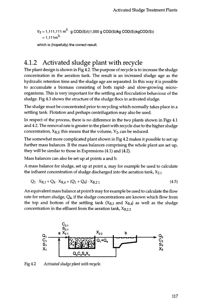
The plant design is shown in Fig 4.2. The purpose of recycle is to increase the sludge
concentration in the aeration tank. The result is an increased sludge age as the
hydraulic retention time and the sludge age are separated. In this way it is possible
to accumulate a biomass consisting of both rapid- and slow-growing microorganisms. This is very important for the settling and flocculation behaviour of the
sludge. Fig 4.3 shows the structure of the sludge floes in activated sludge.
The sludge must be concentrated prior to recycling which normally takes place in a
settling tank. Flotation and perhaps centrifugation may also be used.
In respect of the process, there is no difference in the two plants shown in Figs 4.1
and 4.2. The removal rate is greater in the plant with recycle due to the higher sludge
concentration, Xs,z this means that the volume, V'L can be reduced.
The somewhat more complicated plant shown in Fig 4.2 makes it possible to set up
further mass balances. If the mass balances comprising the whole plant are set up,
they will be similar to those in Expressions (4.1) and (4.2).
Mass balances can also be set up at points a and b.
A mass balance for sludge, set up at point a, may for example be used to calculate
the influent concentration of sludge discharged into the aeration tank, X2.1
(4.5)
An equivalent mass balance at point b may for example be used to calculate the flow
rate for return sludge, Q4. if the sludge concentrations are known which flow from
the top and bottom of the settling tank (XB,3 and Xs,4) as well as the sludge
concentration in the effluent from the aeration tank, Xs,2.2
Fig4.2
Activated sludge plant with recycle.
117
V2 = 1,111,111 m 3 · g COD(S)/((1 ,000 g COD(S)/kg COD(S))kgCOD(S))
= 1,111m 3 ·
which is (hopefully) the correct result.
4.1.2 Activated sludge plant with recycle
The plant design is shown in Fig 4.2. The purpose of recycle is to increase the sludge
concentration in the aeration tank. The result is an increased sludge age as the
hydraulic retention time and the sludge age are separated. In this way it is possible
to accumulate a biomass consisting of both rapid- and slow-growing microorganisms. This is very important for the settling and flocculation behaviour of the
sludge. Fig 4.3 shows the structure of the sludge floes in activated sludge.
The sludge must be concentrated prior to recycling which normally takes place in a
settling tank. Flotation and perhaps centrifugation may also be used.
In respect of the process, there is no difference in the two plants shown in Figs 4.1
and 4.2. The removal rate is greater in the plant with recycle due to the higher sludge
concentration, Xs,z this means that the volume, V'L can be reduced.
The somewhat more complicated plant shown in Fig 4.2 makes it possible to set up
further mass balances. If the mass balances comprising the whole plant are set up,
they will be similar to those in Expressions (4.1) and (4.2).
Mass balances can also be set up at points a and b.
A mass balance for sludge, set up at point a, may for example be used to calculate
the influent concentration of sludge discharged into the aeration tank, X2.1
(4.5)
An equivalent mass balance at point b may for example be used to calculate the flow
rate for return sludge, Q4. if the sludge concentrations are known which flow from
the top and bottom of the settling tank (XB,3 and Xs,4) as well as the sludge
concentration in the effluent from the aeration tank, Xs,2.2
Fig4.2
Activated sludge plant with recycle.
117