

The Water Balance Conveyance Model was developed for this project to capture
the effects of inter-watershed transfers. The model can route water from withdrawal
points to discharge points and represent evaporative and other consumptive losses
and return flows occurring throughout a complex system. The model has sufficient
flexibility to represent situations common in the upper Potomac Basin, such as
interconnections between two or more water distribution systems or wastewater
collection systems, and where self-supplied industrial and commercial users ultimately discharge to public wastewater collection/treatment systems. It can represent both consumptive loss and return to the resource which may occur at the point
of water use. It can represent the losses that often take place at water treatment
plants where the treatment process may involve consumptive evaporative losses
and/or discharges of residual process water back to streams. Finally, it can represent
consumptive losses that may occur at WWTPs in cases where a portion of discharge
is reused for irrigation or other purposes.
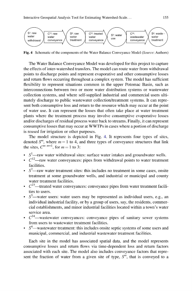
The model structure is depicted in Fig. 4. It represents four types of sites,
denoted S
m , where m ¼ 1 to 4, and three types of conveyance structures that link
the sites, C
m m+1 , for m ¼ 1 to 3:
• S
1 —raw water withdrawal sites: surface water intakes and groundwater wells.
• C
12 —raw water conveyances: pipes from withdrawal points to water treatment
facilities.
• S
2 —raw water treatment sites: this includes no treatment in some cases, onsite
treatment at some groundwater wells, and industrial or municipal and county
water treatment facilities.
• C
23 —treated water conveyances: conveyance pipes from water treatment facilities to users.
• S
3 —water users: water users may be represented as individual users, e.g., an
individual industrial facility, or by a group of users, say, the residents, commercial establishments, and minor industrial facilities located within a town’s water
service area.
• C
34 —wastewater conveyances: conveyance pipes of sanitary sewer systems
from users to wastewater treatment facilities.
• S
4 —wastewater treatment: this includes onsite septic systems of some users and
municipal, commercial, and industrial wastewater treatment facilities.
Each site in the model has associated spatial data, and the model represents
consumptive losses and return flows via time-dependent loss and return factors
associated with each site. The model also includes conveyance factors that represent the fraction of water from a given site of type, S
m , that is conveyed to a
C 12 : raw
water
conveyance
C 23 : treated
water
conveyance
C 34 :
wastewater
conveyance
S 2 : raw
water
treatment
S 1 : raw
water
withdrawal
S 4 : waste -
water
treatment
S 3 : water
use
Fig. 4 Schematic of the components of the Water Balance Conveyance Model (Source: Authors)
Interactive Geospatial Analysis Tool for Estimating Watershed-Scale. . .
155
the effects of inter-watershed transfers. The model can route water from withdrawal
points to discharge points and represent evaporative and other consumptive losses
and return flows occurring throughout a complex system. The model has sufficient
flexibility to represent situations common in the upper Potomac Basin, such as
interconnections between two or more water distribution systems or wastewater
collection systems, and where self-supplied industrial and commercial users ultimately discharge to public wastewater collection/treatment systems. It can represent both consumptive loss and return to the resource which may occur at the point
of water use. It can represent the losses that often take place at water treatment
plants where the treatment process may involve consumptive evaporative losses
and/or discharges of residual process water back to streams. Finally, it can represent
consumptive losses that may occur at WWTPs in cases where a portion of discharge
is reused for irrigation or other purposes.
The model structure is depicted in Fig. 4. It represents four types of sites,
denoted S
m , where m ¼ 1 to 4, and three types of conveyance structures that link
the sites, C
m m+1 , for m ¼ 1 to 3:
• S
1 —raw water withdrawal sites: surface water intakes and groundwater wells.
• C
12 —raw water conveyances: pipes from withdrawal points to water treatment
facilities.
• S
2 —raw water treatment sites: this includes no treatment in some cases, onsite
treatment at some groundwater wells, and industrial or municipal and county
water treatment facilities.
• C
23 —treated water conveyances: conveyance pipes from water treatment facilities to users.
• S
3 —water users: water users may be represented as individual users, e.g., an
individual industrial facility, or by a group of users, say, the residents, commercial establishments, and minor industrial facilities located within a town’s water
service area.
• C
34 —wastewater conveyances: conveyance pipes of sanitary sewer systems
from users to wastewater treatment facilities.
• S
4 —wastewater treatment: this includes onsite septic systems of some users and
municipal, commercial, and industrial wastewater treatment facilities.
Each site in the model has associated spatial data, and the model represents
consumptive losses and return flows via time-dependent loss and return factors
associated with each site. The model also includes conveyance factors that represent the fraction of water from a given site of type, S
m , that is conveyed to a
C 12 : raw
water
conveyance
C 23 : treated
water
conveyance
C 34 :
wastewater
conveyance
S 2 : raw
water
treatment
S 1 : raw
water
withdrawal
S 4 : waste -
water
treatment
S 3 : water
use
Fig. 4 Schematic of the components of the Water Balance Conveyance Model (Source: Authors)
Interactive Geospatial Analysis Tool for Estimating Watershed-Scale. . .
155