

396
Related Techniques
o
£"7\ ..
u" 1 AWl.
... ...
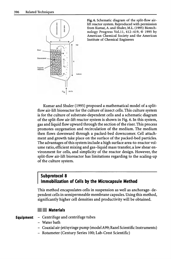
Fig. 6. Schematic diagram of the split-flow airlift reactor system. Reproduced with permission
from Kumar, A. and Shuler, M.L. (1995) Biotechnology Progress Vol.ll, 412-419, © 1995 by
American Chemical Society and the American
Institute of Chemical Engineers
Kumar and Shuler (1995) proposed a mathematical model of a splitflow air-lift bioreactor for the culture of insect cells. This culture system
is for the culture of substrate-dependent cells and a schematic diagram
of the split-flow air-lift reactor system is shown in Fig. 6. In this system,
gas and liquid flow upward through the section of the riser. This process
promotes oxygenation and recirculation of the medium. The medium
then flows downward through a packed-bed downcomer. Cell attachment and growth take place on the surface of the packed-bed particles.
The advantages of this system include a high surface area-to-reactor volume ratio, efficient mixing and gas-liquid mass transfer, a low shear environment for cells, and simplicity of the reactor design. However, the
split-flow air-lift bioreactor has limitations regarding to the scaling-up
of the culture system.
Subprotocol 8
Immobilization of Cells by the Microcapsule Method
This method encapsulates cells in suspension as well as anchorage- dependent cells in semipermeable membrane capsules. Using this method,
significantly higher cell densities and productivity will be obtained .
• • Materials
Equipment - Centrifuge and centrifuge tubes
- Water bath
- Coaxial air-jet/syringe pump (modelA99; Razel Scientific Instruments)
- Rotameter (Century Series 100; Lab-Crest Scientific)
Related Techniques
o
£"7\ ..
u" 1 AWl.
... ...
Fig. 6. Schematic diagram of the split-flow airlift reactor system. Reproduced with permission
from Kumar, A. and Shuler, M.L. (1995) Biotechnology Progress Vol.ll, 412-419, © 1995 by
American Chemical Society and the American
Institute of Chemical Engineers
Kumar and Shuler (1995) proposed a mathematical model of a splitflow air-lift bioreactor for the culture of insect cells. This culture system
is for the culture of substrate-dependent cells and a schematic diagram
of the split-flow air-lift reactor system is shown in Fig. 6. In this system,
gas and liquid flow upward through the section of the riser. This process
promotes oxygenation and recirculation of the medium. The medium
then flows downward through a packed-bed downcomer. Cell attachment and growth take place on the surface of the packed-bed particles.
The advantages of this system include a high surface area-to-reactor volume ratio, efficient mixing and gas-liquid mass transfer, a low shear environment for cells, and simplicity of the reactor design. However, the
split-flow air-lift bioreactor has limitations regarding to the scaling-up
of the culture system.
Subprotocol 8
Immobilization of Cells by the Microcapsule Method
This method encapsulates cells in suspension as well as anchorage- dependent cells in semipermeable membrane capsules. Using this method,
significantly higher cell densities and productivity will be obtained .
• • Materials
Equipment - Centrifuge and centrifuge tubes
- Water bath
- Coaxial air-jet/syringe pump (modelA99; Razel Scientific Instruments)
- Rotameter (Century Series 100; Lab-Crest Scientific)