

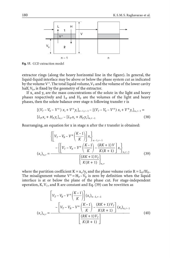
extractor rings (along the heavy horizontal line in the figure). In general, the
liquid-liquid interface may be above or below the phase system cut as indicated
by the volume V *. The total liquid volume,V T and the volume of the lower cavity
half, V b , is fixed by the geometry of the extractor.
If x s and y s are the mass concentrations of the solute in the light and heavy
phases respectively and L P and H P are the volumes of the light and heavy
phases, then the solute balance over stage n following transfer r is
[(V T – V b – V *) x s + V *y s ] n –1,r –1 – [(V T – V b – V *) x s + V *y s ] n, r –1 =
[L P x s + H P y s ] n,r – [L P x s + H P y s ] n,r –1
(38)
Rearranging, an equation for x in stage n after the r transfer is obtained:
K – 1
Ά΄ V T – V B – V* 71 ΅ x s ·
K
n –1, r –1
K – 1 (RK + 1)V
– Ά΄ V T – V B – V* 71 – 08 ΅ x s ·
K
K(R + 1)
n, r –1
(x s ) n, r = 000000001
(39)
(RK + 1)V T
Ά 7101 ·
K(R + 1) n, r
where the partition coefficient K = x s /y s and the phase volume ratio R = L P /H P .
The misalignment volume V * = H P –V B is zero by definition when the liquid
interface is at or below the plane of the phase cut. For stage-independent
operation, K, V T , and R are constant and Eq. (39) can be rewritten as
K – 1
΄ V T – V B – V* 71 ΅ (x s ) n –1, r –1
K
K – 1 (RK + 1)V T
– ΄ V T – V B – V* 71 – 081 ΅ (x s ) n, r –1
K
K(R + 1)
(x s ) n, r = 0000000543
(40)
(RK + 1)V T
΄ 7101 ΅
K(R + 1)
180
K.S.M.S. Raghavarao et al.
Fig. 17. CCD extraction model
liquid-liquid interface may be above or below the phase system cut as indicated
by the volume V *. The total liquid volume,V T and the volume of the lower cavity
half, V b , is fixed by the geometry of the extractor.
If x s and y s are the mass concentrations of the solute in the light and heavy
phases respectively and L P and H P are the volumes of the light and heavy
phases, then the solute balance over stage n following transfer r is
[(V T – V b – V *) x s + V *y s ] n –1,r –1 – [(V T – V b – V *) x s + V *y s ] n, r –1 =
[L P x s + H P y s ] n,r – [L P x s + H P y s ] n,r –1
(38)
Rearranging, an equation for x in stage n after the r transfer is obtained:
K – 1
Ά΄ V T – V B – V* 71 ΅ x s ·
K
n –1, r –1
K – 1 (RK + 1)V
– Ά΄ V T – V B – V* 71 – 08 ΅ x s ·
K
K(R + 1)
n, r –1
(x s ) n, r = 000000001
(39)
(RK + 1)V T
Ά 7101 ·
K(R + 1) n, r
where the partition coefficient K = x s /y s and the phase volume ratio R = L P /H P .
The misalignment volume V * = H P –V B is zero by definition when the liquid
interface is at or below the plane of the phase cut. For stage-independent
operation, K, V T , and R are constant and Eq. (39) can be rewritten as
K – 1
΄ V T – V B – V* 71 ΅ (x s ) n –1, r –1
K
K – 1 (RK + 1)V T
– ΄ V T – V B – V* 71 – 081 ΅ (x s ) n, r –1
K
K(R + 1)
(x s ) n, r = 0000000543
(40)
(RK + 1)V T
΄ 7101 ΅
K(R + 1)
180
K.S.M.S. Raghavarao et al.
Fig. 17. CCD extraction model