

cause a cell reaction then is to boost the external voltage to a sufficiently high level
or to establish an input signal through the dendritic connections.
The Fitzhugh–Nagumo equations used here have been adapted from Brown and
Rothery [1] and are
dV=dt ¼ ÀV Ã V À V1
ð
ÞÃ V À V2
ð
ÞÀW þ E ¼ current,
ð11:1Þ
dW=dt ¼ EPSILON Ã V À C Ã W
ð
Þ
ð 11:2Þ
where V is the departure of the membrane potential from its equilibrium and W is
the recovery current reflecting conductance of ions depending on voltage. These
two variables are the state variables of the system. The amplifying threshold
parameters V1 and V2 capture the influence of V on the rate of change of V and
are held constant at 0.2 and 1.0, respectively. The parameter E reflects the electrical
current to which the neuron is exposed.
Equations (11.1) and (11.2) can be combined into a single second order differential equation: the rate of change of velocity of the membrane potential voltage.
The amplifying character of the neuron is analogous to function of the transistor.
The rate of change of the recovery variable W, defined in Eq. (11.2), is dependent
on the difference between the departure of the membrane potential from its
equilibrium V, and the recovery variable W that decays at a constant rate C. In
our model, we arbitrarily set C ¼ 0.5. The change in W is assumed to be proportional to (V À C * W), with a proportionality factor of EPSILON. We set
EPSILON ¼ 0.02.
The STELLA model of the Fitzhugh–Nagumo equations is shown in Fig. 11.2.
Note that in this STELLA model, the control flows are set up as biflows and the
stocks are set to allow negative values. We run this model at a DT ¼ 0.1, using the
Euler integration method.
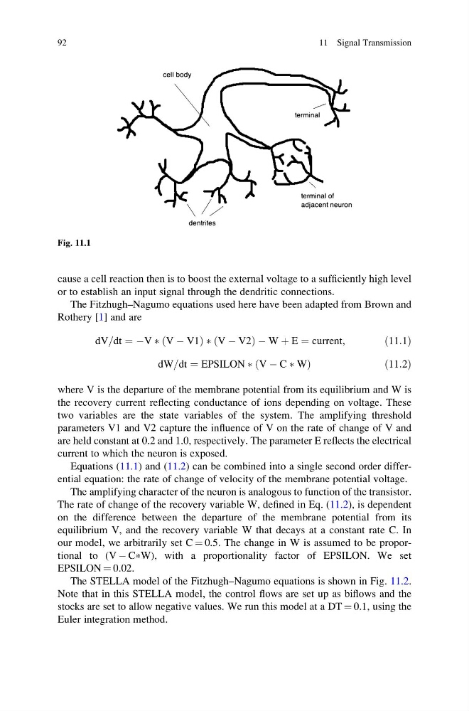
Fig. 11.1
92
11 Signal Transmission
or to establish an input signal through the dendritic connections.
The Fitzhugh–Nagumo equations used here have been adapted from Brown and
Rothery [1] and are
dV=dt ¼ ÀV Ã V À V1
ð
ÞÃ V À V2
ð
ÞÀW þ E ¼ current,
ð11:1Þ
dW=dt ¼ EPSILON Ã V À C Ã W
ð
Þ
ð 11:2Þ
where V is the departure of the membrane potential from its equilibrium and W is
the recovery current reflecting conductance of ions depending on voltage. These
two variables are the state variables of the system. The amplifying threshold
parameters V1 and V2 capture the influence of V on the rate of change of V and
are held constant at 0.2 and 1.0, respectively. The parameter E reflects the electrical
current to which the neuron is exposed.
Equations (11.1) and (11.2) can be combined into a single second order differential equation: the rate of change of velocity of the membrane potential voltage.
The amplifying character of the neuron is analogous to function of the transistor.
The rate of change of the recovery variable W, defined in Eq. (11.2), is dependent
on the difference between the departure of the membrane potential from its
equilibrium V, and the recovery variable W that decays at a constant rate C. In
our model, we arbitrarily set C ¼ 0.5. The change in W is assumed to be proportional to (V À C * W), with a proportionality factor of EPSILON. We set
EPSILON ¼ 0.02.
The STELLA model of the Fitzhugh–Nagumo equations is shown in Fig. 11.2.
Note that in this STELLA model, the control flows are set up as biflows and the
stocks are set to allow negative values. We run this model at a DT ¼ 0.1, using the
Euler integration method.
Fig. 11.1
92
11 Signal Transmission