

18 Field Radiometry and Ocean Color Remote Sensing
309
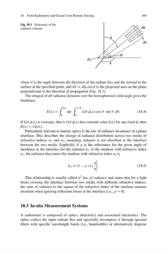
Fig. 18.1 Schematic of the
radiance concept
where θ is the angle between the direction of the radiant flux and the normal to the
surface at the specified point, and dS = dS 0 cos θ is the projected area on the plane
perpendicular to the direction of propagation (Fig. 18.1).
The integral of all radiance elements over the hemispherical solid angle gives the
irradiance
E(λ) =
2π
0
dφ
π/2
0
L(θ ,φ,λ) cos θ sin θ dθ.
(18.4)
If L(θ ,φ,λ) is isotropic, that is L(θ ,φ,λ) has constant value L(λ) for any θand φ, then
E(λ) = π L(λ).
Particularly relevant to marine optics is the law of radiance invariance at a plane
interface. This describes the change in radiance distribution across two media of
refractive indices n 1 and n 2 , assuming radiance is not absorbed at the interface
between the two media. Explicitly, if ρ is the reflectance for the given angle of
incidence at the interface for the radiance L 1 in the medium with refractive index
n 1 , the radiance that enters the medium with refractive index n 2 is
L 2 = (1 − ρ ) L 1
n 2
2
n 2
1
.
(18.5)
This relationship is usually called n 2 law of radiance and states that for a light
beam crossing the interface between two media with different refractive indices,
the ratio of radiance to the square of the refractive index of the medium remains
invariant when ignoring reflection losses at the interface (i.e., ρ = 0).
18.3 In-situ Measurement Systems
A radiometer is composed of optics, detector(s) and associated electronics. The
optics collect the input radiant flux and spectrally decompose it through spectral
filters with specific wavelength bands (i.e., bandwidths) or alternatively disperse
309
Fig. 18.1 Schematic of the
radiance concept
where θ is the angle between the direction of the radiant flux and the normal to the
surface at the specified point, and dS = dS 0 cos θ is the projected area on the plane
perpendicular to the direction of propagation (Fig. 18.1).
The integral of all radiance elements over the hemispherical solid angle gives the
irradiance
E(λ) =
2π
0
dφ
π/2
0
L(θ ,φ,λ) cos θ sin θ dθ.
(18.4)
If L(θ ,φ,λ) is isotropic, that is L(θ ,φ,λ) has constant value L(λ) for any θand φ, then
E(λ) = π L(λ).
Particularly relevant to marine optics is the law of radiance invariance at a plane
interface. This describes the change in radiance distribution across two media of
refractive indices n 1 and n 2 , assuming radiance is not absorbed at the interface
between the two media. Explicitly, if ρ is the reflectance for the given angle of
incidence at the interface for the radiance L 1 in the medium with refractive index
n 1 , the radiance that enters the medium with refractive index n 2 is
L 2 = (1 − ρ ) L 1
n 2
2
n 2
1
.
(18.5)
This relationship is usually called n 2 law of radiance and states that for a light
beam crossing the interface between two media with different refractive indices,
the ratio of radiance to the square of the refractive index of the medium remains
invariant when ignoring reflection losses at the interface (i.e., ρ = 0).
18.3 In-situ Measurement Systems
A radiometer is composed of optics, detector(s) and associated electronics. The
optics collect the input radiant flux and spectrally decompose it through spectral
filters with specific wavelength bands (i.e., bandwidths) or alternatively disperse