

134
R.H. Charlier and Chr. P. De Meyer
O~'L~ve~
Y~
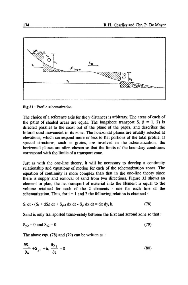
Fig 31 : Profile schematization
The choice of a reference axis for the y distances is arbitrary. The areas of each of
the pairs of shaded areas are equal. The longshore transport Si (i = 1, 2) is
directed parallel to the coast out of the plane of the paper, and describes the
littoral sand movement in its zone. The horizontal planes are usually selected at
elevations, which correspond more or less to fiat portions of the total profile. If
special structures, such as groins, are involved in the schematization, the
horizontal planes are often chosen so that the limits of the boundary conditions
correspond with the limits of a transport zone.
Just as with the one-line theory, it will be necessary to develop a continuity
relationship and equations of motion for each of the schematization zones. The
equation of continuity is more complex than that in the one-line theory since
there is supply and removal of sand from two directions. Figure 32 shows an
element in plan; the net transport of material into the element is equal to the
volume retained for each of the 2 elements - one for each line of the
schematization. Thus, for i = 1 and 2 the following relation is obtained :
Si dt - (Si + dSi) dt + Syi.l dx dt - Syi dx dt = dx dyi hi
(78)
Sand is only transported transversely between the first and second zone so that :
Syo = 0 and Sy2 = 0
(79)
The above eqs. (78) and (79) can be written as"
aS 1
aY 1
-+Sy I +h I .............. 0
(80)
Ox
at
R.H. Charlier and Chr. P. De Meyer
O~'L~ve~
Y~
Fig 31 : Profile schematization
The choice of a reference axis for the y distances is arbitrary. The areas of each of
the pairs of shaded areas are equal. The longshore transport Si (i = 1, 2) is
directed parallel to the coast out of the plane of the paper, and describes the
littoral sand movement in its zone. The horizontal planes are usually selected at
elevations, which correspond more or less to fiat portions of the total profile. If
special structures, such as groins, are involved in the schematization, the
horizontal planes are often chosen so that the limits of the boundary conditions
correspond with the limits of a transport zone.
Just as with the one-line theory, it will be necessary to develop a continuity
relationship and equations of motion for each of the schematization zones. The
equation of continuity is more complex than that in the one-line theory since
there is supply and removal of sand from two directions. Figure 32 shows an
element in plan; the net transport of material into the element is equal to the
volume retained for each of the 2 elements - one for each line of the
schematization. Thus, for i = 1 and 2 the following relation is obtained :
Si dt - (Si + dSi) dt + Syi.l dx dt - Syi dx dt = dx dyi hi
(78)
Sand is only transported transversely between the first and second zone so that :
Syo = 0 and Sy2 = 0
(79)
The above eqs. (78) and (79) can be written as"
aS 1
aY 1
-+Sy I +h I .............. 0
(80)
Ox
at