

10
Exercise 1
maximum length:
Area (A). The area of the surface and of each contour interval at depth z may be determined by
a digitizer or planimetry of a detailed bathymetric map. Computers with appropriate software
and other electronic devices are available to digitize and measure two-dimensional distributions
of data such as line graphs, maps, etc. (e.g., Sigma Scan measurement systems. landel Scientific,
Sausalito, CAl. A less precise but effective method is by a grid enumeration analysis [cf., Olson
(1960)].
A polar planimeter is an ingenious but relatively inexpensive instrument that permits an
integration of the area of any plane surface regardless of its shape. A planimeter consists of two
units: the pole arm unit and the tracer arm-carriage unit. The tracer arm, containing the tracer
point and magnifying lens, connects to the carriage unit. The carriage unit consists of a dial, a
vernier, a measuring wheel, a support wheel, and a zero-setting wheel.
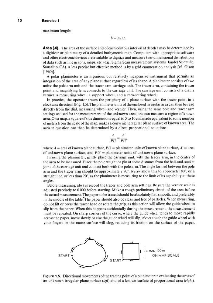
In practice, the operator traces the periphery of a plane surface with the tracer point in a
clockwise direction (Fig. 1.5). The planimeter units of the enclosed irregular area can then be read
directly from the dial, measuring wheel, and vernier. Then, using the same pole and tracer arm
settings as used for the measurement of the unknown area, one can measure a region of known
area. On a map, a square of side dimensions equal to 5 to 10 cm, made equivalent to some number
of meters from the scale of the map, makes a convenient regular plane surface of known area. The
area in question can then be determined by a direct proportional equation:
A
A'
PU PU'
where A = area of known plane surface, PU = planimeter units of known plane surface, A' = area
of unknown plane surface, and PU' = planimeter units of unknown plane surface.
In using the planimeter, gently place the carriage unit, with the tracer arm, in the center of
the area to be measured. Place the pole weight or pin at some distance from the ball-and-socket
joint of the carriage unit and connect both with the pole arm. The angle formed between the pole
arm and the tracer arm should be approximately 90°. Never allow this to approach 180°, or a
straight line, or less than 20°, as the planimeter is measuring to the limit of its capability at these
angles.
Before measuring, always record the tracer and pole arm settings. Be sure the vernier scale is
adjusted precisely to 0.000 before starting. Make a rough preliminary circuit of the area before
the actual measurement. The paper to be traced should be absolutely flat, smooth, and preferably
in the middle of the table.·The paper should also be clean and free of particles. When measuring,
do not lift or press the tracer head or rotate the grip, as this action will allow the guide wheel to
slip from the paper. When this happens accidentally during the measurement, the measurement
must be repeated. On sharp corners of the curve, where the guide wheel tends to move rapidly
across the paper, move slowly or else the guide wheel will slip. Never touch the guide wheel with
your fingers or the matte surface will clog, reducing its friction on the surface of the paper.
START
'0-1
{) START
-
1
= e.g. 100m
ON MAP SCALE
Figure 1.5. Directional movements of the tracing point of a planimeter in evaluating the areas of
an unknown irregular plane surface (left) and of a known surface of proportional area (right).
Exercise 1
maximum length:
Area (A). The area of the surface and of each contour interval at depth z may be determined by
a digitizer or planimetry of a detailed bathymetric map. Computers with appropriate software
and other electronic devices are available to digitize and measure two-dimensional distributions
of data such as line graphs, maps, etc. (e.g., Sigma Scan measurement systems. landel Scientific,
Sausalito, CAl. A less precise but effective method is by a grid enumeration analysis [cf., Olson
(1960)].
A polar planimeter is an ingenious but relatively inexpensive instrument that permits an
integration of the area of any plane surface regardless of its shape. A planimeter consists of two
units: the pole arm unit and the tracer arm-carriage unit. The tracer arm, containing the tracer
point and magnifying lens, connects to the carriage unit. The carriage unit consists of a dial, a
vernier, a measuring wheel, a support wheel, and a zero-setting wheel.
In practice, the operator traces the periphery of a plane surface with the tracer point in a
clockwise direction (Fig. 1.5). The planimeter units of the enclosed irregular area can then be read
directly from the dial, measuring wheel, and vernier. Then, using the same pole and tracer arm
settings as used for the measurement of the unknown area, one can measure a region of known
area. On a map, a square of side dimensions equal to 5 to 10 cm, made equivalent to some number
of meters from the scale of the map, makes a convenient regular plane surface of known area. The
area in question can then be determined by a direct proportional equation:
A
A'
PU PU'
where A = area of known plane surface, PU = planimeter units of known plane surface, A' = area
of unknown plane surface, and PU' = planimeter units of unknown plane surface.
In using the planimeter, gently place the carriage unit, with the tracer arm, in the center of
the area to be measured. Place the pole weight or pin at some distance from the ball-and-socket
joint of the carriage unit and connect both with the pole arm. The angle formed between the pole
arm and the tracer arm should be approximately 90°. Never allow this to approach 180°, or a
straight line, or less than 20°, as the planimeter is measuring to the limit of its capability at these
angles.
Before measuring, always record the tracer and pole arm settings. Be sure the vernier scale is
adjusted precisely to 0.000 before starting. Make a rough preliminary circuit of the area before
the actual measurement. The paper to be traced should be absolutely flat, smooth, and preferably
in the middle of the table.·The paper should also be clean and free of particles. When measuring,
do not lift or press the tracer head or rotate the grip, as this action will allow the guide wheel to
slip from the paper. When this happens accidentally during the measurement, the measurement
must be repeated. On sharp corners of the curve, where the guide wheel tends to move rapidly
across the paper, move slowly or else the guide wheel will slip. Never touch the guide wheel with
your fingers or the matte surface will clog, reducing its friction on the surface of the paper.
START
'0-1
{) START
-
1
= e.g. 100m
ON MAP SCALE
Figure 1.5. Directional movements of the tracing point of a planimeter in evaluating the areas of
an unknown irregular plane surface (left) and of a known surface of proportional area (right).