

24
H. Rott
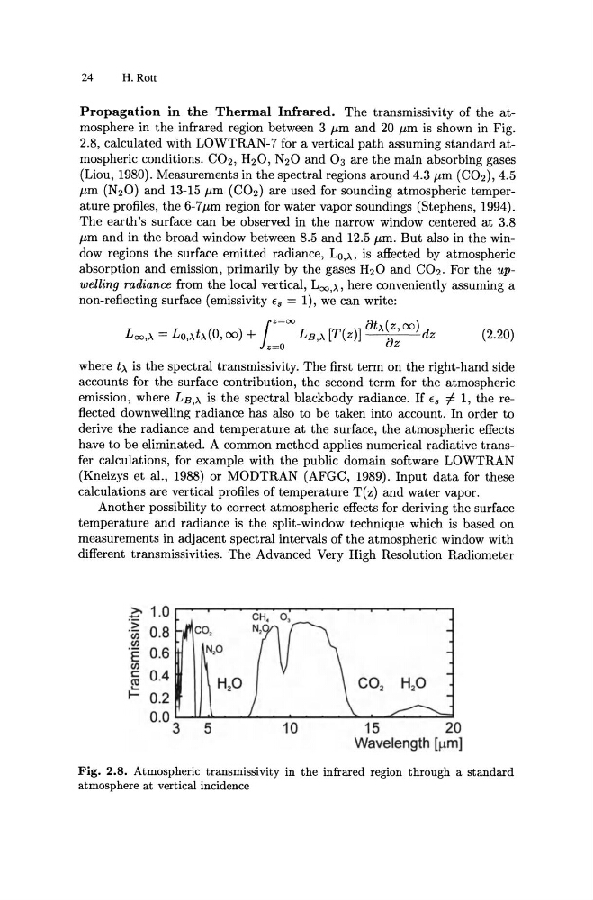
Propagation in the Thermal Infrared. The transmissivity of the atmosphere in the infrared region between 3 J1.m and 20 J1.m is shown in Fig.
2.8, calculated with LOWTRAN-7 for a vertical path assuming standard atmospheric conditions. CO2 , H2 0, N20 and 0 3 are the main absorbing gases
(Liou, 1980). Measurements in the spectral regions around 4.3 J1.m (C02 ), 4.5
J1.m (N2 0) and 13-15 J1.m (C02 ) are used for sounding atmospheric temperature profiles, the 6-7J1.m region for water vapor soundings (Stephens, 1994).
The earth's surface can be observed in the narrow window centered at 3.8
J1.m and in the broad window between 8.5 and 12.5 J1.m. But also in the window regions the surface emitted radiance, Lo,)" is affected by atmospheric
absorption and emission, primarily by the gases H2 0 and CO2 . For the upwelling radiance from the local vertical, Loo,)" here conveniently assuming a
non-reflecting surface (emissivity fa = 1) , we can write:
l
z =oo
at (z 00)
L oo ,), = Lo,),t),(O, 00) + z=O LB ,), [T(z)] ), a; dz (2.20)
where t), is the spectral transmissivity. The first term on the right-hand side
accounts for the surface contribution, the second term for the atmospheric
emission, where LB,)' is the spectral blackbody radiance. If fa =j:. 1, the reflected downwelling radiance has also to be taken into account. In order to
derive the radiance and temperature at the surface, the atmospheric effects
have to be eliminated. A common method applies numerical radiative transfer calculations, for example with the public domain software LOWTRAN
(Kneizys et al., 1988) or MODTRAN (AFGC, 1989) . Input data for these
calculations are vertical profiles of temperature T(z) and water vapor.
Another possibility to correct atmospheric effects for deriving the surface
temperature and radiance is the split-window technique which is based on
measurements in adjacent spectral intervals of the atmospheric window with
different transmissivities. The Advanced Very High Resolution Radiometer
>. 1.0
-
.::; 0.8
.(i)
(J)
·e 0.6
(J)
c: 0.4
HP
~
~ 0.2
0.0 3 5
10
15
20
Wavelength [llm]
Fig. 2.8. Atmospheric transmissivity in the infrared region through a standard
atmosphere at vertical incidence
H. Rott
Propagation in the Thermal Infrared. The transmissivity of the atmosphere in the infrared region between 3 J1.m and 20 J1.m is shown in Fig.
2.8, calculated with LOWTRAN-7 for a vertical path assuming standard atmospheric conditions. CO2 , H2 0, N20 and 0 3 are the main absorbing gases
(Liou, 1980). Measurements in the spectral regions around 4.3 J1.m (C02 ), 4.5
J1.m (N2 0) and 13-15 J1.m (C02 ) are used for sounding atmospheric temperature profiles, the 6-7J1.m region for water vapor soundings (Stephens, 1994).
The earth's surface can be observed in the narrow window centered at 3.8
J1.m and in the broad window between 8.5 and 12.5 J1.m. But also in the window regions the surface emitted radiance, Lo,)" is affected by atmospheric
absorption and emission, primarily by the gases H2 0 and CO2 . For the upwelling radiance from the local vertical, Loo,)" here conveniently assuming a
non-reflecting surface (emissivity fa = 1) , we can write:
l
z =oo
at (z 00)
L oo ,), = Lo,),t),(O, 00) + z=O LB ,), [T(z)] ), a; dz (2.20)
where t), is the spectral transmissivity. The first term on the right-hand side
accounts for the surface contribution, the second term for the atmospheric
emission, where LB,)' is the spectral blackbody radiance. If fa =j:. 1, the reflected downwelling radiance has also to be taken into account. In order to
derive the radiance and temperature at the surface, the atmospheric effects
have to be eliminated. A common method applies numerical radiative transfer calculations, for example with the public domain software LOWTRAN
(Kneizys et al., 1988) or MODTRAN (AFGC, 1989) . Input data for these
calculations are vertical profiles of temperature T(z) and water vapor.
Another possibility to correct atmospheric effects for deriving the surface
temperature and radiance is the split-window technique which is based on
measurements in adjacent spectral intervals of the atmospheric window with
different transmissivities. The Advanced Very High Resolution Radiometer
>. 1.0
-
.::; 0.8
.(i)
(J)
·e 0.6
(J)
c: 0.4
HP
~
~ 0.2
0.0 3 5
10
15
20
Wavelength [llm]
Fig. 2.8. Atmospheric transmissivity in the infrared region through a standard
atmosphere at vertical incidence