

116
C.G. Collier
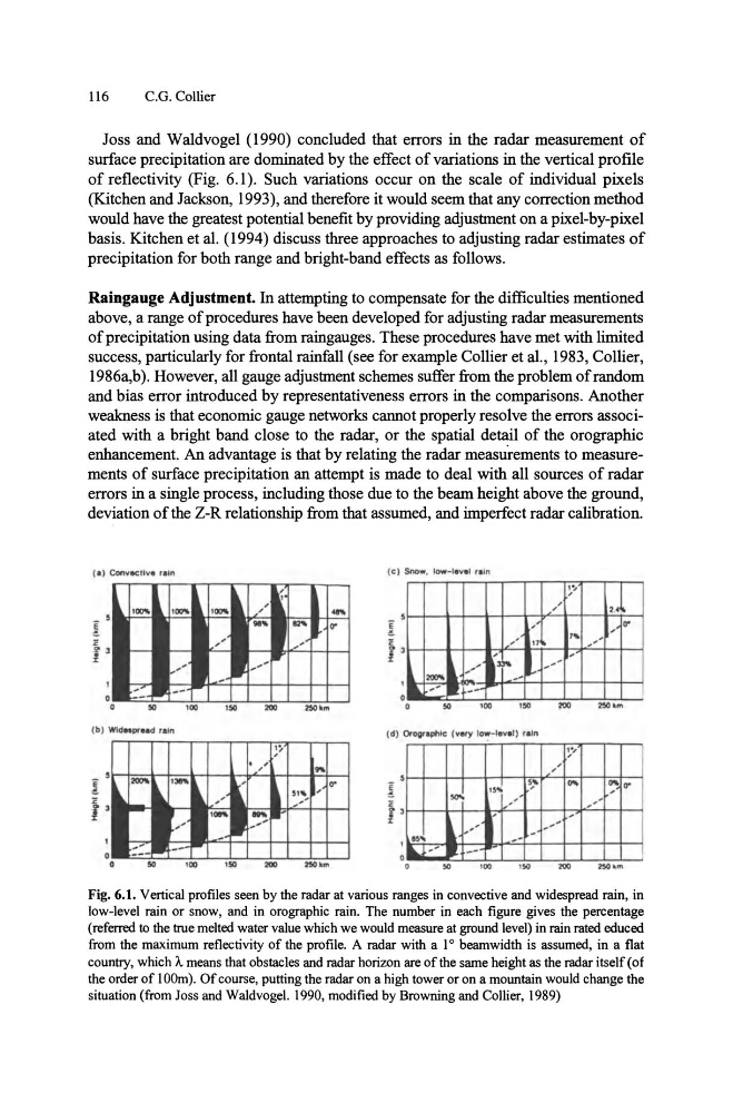
Joss and Waldvogel (1990) concluded that errors in the radar measurement of
surface precipitation are dominated by the effect of variations in the vertical profile
of reflectivity (Fig. 6.1). Such variations occur on the scale of individual pixels
(Kitchen and Jackson, 1993), and therefore it would seem that any correction method
would have the greatest potential benefit by providing adjustment on a pixel-by-pixel
basis. Kitchen et al. (1994) discuss three approaches to adjusting radar estimates of
precipitation for both range and bright-band effects as follows.
Raingauge Adjustment. In attempting to compensate for the difficulties mentioned
above, a range of procedures have been developed for adjusting radar measurements
of precipitation using data from raingauges. These procedures have met with limited
success, particularly for frontal rainfall (see for example Collier et aI., 1983, Collier,
1986a,b). However, all gauge adjustment schemes suffer from the problem of random
and bias error introduced by representativeness errors in the comparisons. Another
weakness is that economic gauge networks cannot properly resolve the errors associated with a bright band close to the radar, or the spatial detail of the orographic
enhancement. An advantage is that by relating the radar measurements to measurements of surface precipitation an attempt is made to deal with all sources of radar
errors in a single process, including those due to the beam height above the ground,
deviation of the Z-R relationship from that assumed, and imperfect radar calibration.
o
o
~
-
"7""
-1 ....
f-/
-100
(b) WldHP' •• d rain
,
1
.""'" ~
L
" ,
,
150
'"'
,l5O'm
•
o
o
5
....
1
..
o
o
20000
/
,
-
~.,
,
.~ , '
,
0"
,
,
'"
, ,
, ,
,
t3~ __
,
l,,/
J.-" /
....
R ~- -
100
150
250 ' m
~.,
,
,
,,~
' ,"
... ~ o......
,
, /
,
r
,
~. "
,,
-- -
. . -'00
.,.
Fig. 6.1. Vertical profiles seen by the radar at various ranges in convective and widespread rain, in
low-level rain or snow, and in orographic rain. The number in each figure gives the percentage
(referred to the true melted water value which we would measure at ground level) in rain rated educed
from the maximum reflectivity of the profile. A radar with a 1 0 beamwidth is assumed, in a flat
country, which A means that obstacles and radar horizon are of the same height as the radar itself (of
the order of 100m). Of course, putting the radar on a high tower or on a mountain would change the
situation (from Joss and Waldvogel. 1990, modified by Browning and Collier, 1989)
C.G. Collier
Joss and Waldvogel (1990) concluded that errors in the radar measurement of
surface precipitation are dominated by the effect of variations in the vertical profile
of reflectivity (Fig. 6.1). Such variations occur on the scale of individual pixels
(Kitchen and Jackson, 1993), and therefore it would seem that any correction method
would have the greatest potential benefit by providing adjustment on a pixel-by-pixel
basis. Kitchen et al. (1994) discuss three approaches to adjusting radar estimates of
precipitation for both range and bright-band effects as follows.
Raingauge Adjustment. In attempting to compensate for the difficulties mentioned
above, a range of procedures have been developed for adjusting radar measurements
of precipitation using data from raingauges. These procedures have met with limited
success, particularly for frontal rainfall (see for example Collier et aI., 1983, Collier,
1986a,b). However, all gauge adjustment schemes suffer from the problem of random
and bias error introduced by representativeness errors in the comparisons. Another
weakness is that economic gauge networks cannot properly resolve the errors associated with a bright band close to the radar, or the spatial detail of the orographic
enhancement. An advantage is that by relating the radar measurements to measurements of surface precipitation an attempt is made to deal with all sources of radar
errors in a single process, including those due to the beam height above the ground,
deviation of the Z-R relationship from that assumed, and imperfect radar calibration.
o
o
~
-
"7""
-1 ....
f-/
-100
(b) WldHP' •• d rain
,
1
.""'" ~
L
" ,
,
150
'"'
,l5O'm
•
o
o
5
....
1
..
o
o
20000
/
,
-
~.,
,
.~ , '
,
0"
,
,
'"
, ,
, ,
,
t3~ __
,
l,,/
J.-" /
....
R ~- -
100
150
250 ' m
~.,
,
,
,,~
' ,"
... ~ o......
,
, /
,
r
,
~. "
,,
-- -
. . -'00
.,.
Fig. 6.1. Vertical profiles seen by the radar at various ranges in convective and widespread rain, in
low-level rain or snow, and in orographic rain. The number in each figure gives the percentage
(referred to the true melted water value which we would measure at ground level) in rain rated educed
from the maximum reflectivity of the profile. A radar with a 1 0 beamwidth is assumed, in a flat
country, which A means that obstacles and radar horizon are of the same height as the radar itself (of
the order of 100m). Of course, putting the radar on a high tower or on a mountain would change the
situation (from Joss and Waldvogel. 1990, modified by Browning and Collier, 1989)