

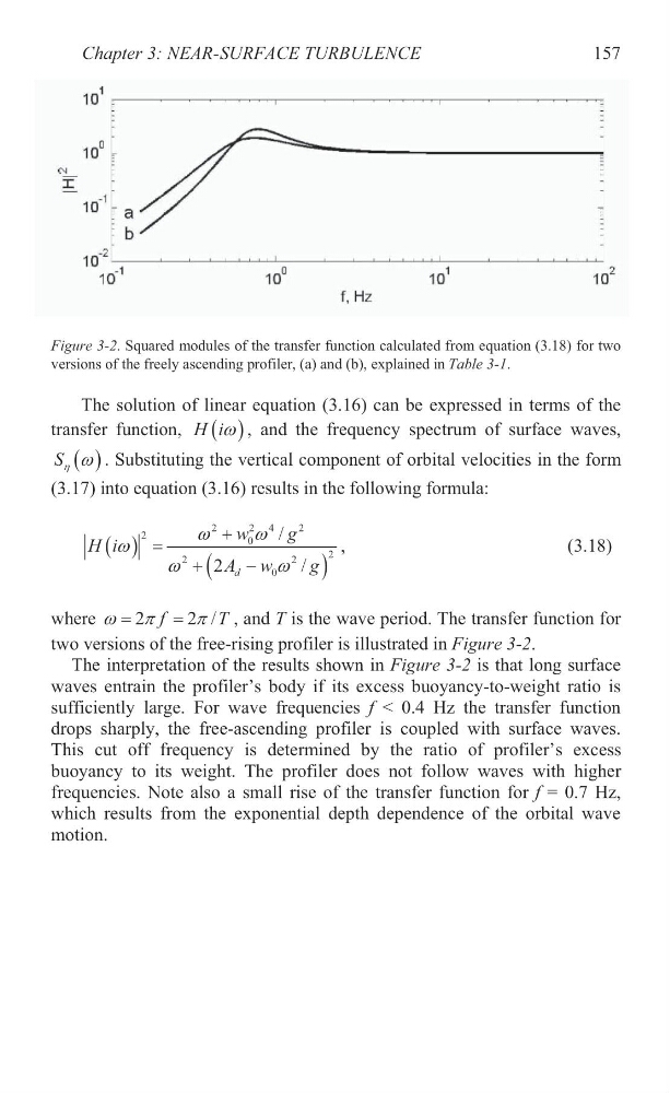
Figure 3-2. Squared modules of the transfer function calculated from equation (3.18) for two
versions of the freely ascending profiler, (a) and (b), explained in Table 3-1.
The solution of linear equation (3.16) can be expressed in terms of the
transfer function,
H iZ , and the frequency spectrum of surface waves,
S K Z . Substituting the vertical component of orbital velocities in the form
(3.17) into equation (3.16) results in the following formula:
2
2 4
2
2
0
2
2
2
0
/
2
/
d
w
g
H i
A w
g
Z
Z
Z
Z
Z
,
(3.18)
where
2
2 /
f
T
Z S
S , and T is the wave period. The transfer function for
two versions of the free-rising profiler is illustrated in Figure 3-2.
The interpretation of the results shown in Figure 3-2 is that long surface
waves entrain the profiler’s body if its excess buoyancy-to-weight ratio is
sufficiently large. For wave frequencies f < 0.4 Hz the transfer function
drops sharply, the free-ascending profiler is coupled with surface waves.
This cut off frequency is determined by the ratio of profiler’s excess
buoyancy to its weight. The profiler does not follow waves with higher
frequencies. Note also a small rise of the transfer function for f = 0.7 Hz,
which results from the exponential depth dependence of the orbital wave
motion.
Chapter 3: NEAR-SURFACE TURBULENCE
157
versions of the freely ascending profiler, (a) and (b), explained in Table 3-1.
The solution of linear equation (3.16) can be expressed in terms of the
transfer function,
H iZ , and the frequency spectrum of surface waves,
S K Z . Substituting the vertical component of orbital velocities in the form
(3.17) into equation (3.16) results in the following formula:
2
2 4
2
2
0
2
2
2
0
/
2
/
d
w
g
H i
A w
g
Z
Z
Z
Z
Z
,
(3.18)
where
2
2 /
f
T
Z S
S , and T is the wave period. The transfer function for
two versions of the free-rising profiler is illustrated in Figure 3-2.
The interpretation of the results shown in Figure 3-2 is that long surface
waves entrain the profiler’s body if its excess buoyancy-to-weight ratio is
sufficiently large. For wave frequencies f < 0.4 Hz the transfer function
drops sharply, the free-ascending profiler is coupled with surface waves.
This cut off frequency is determined by the ratio of profiler’s excess
buoyancy to its weight. The profiler does not follow waves with higher
frequencies. Note also a small rise of the transfer function for f = 0.7 Hz,
which results from the exponential depth dependence of the orbital wave
motion.
Chapter 3: NEAR-SURFACE TURBULENCE
157