

Part C | 32.4
728 Part C Coastal Design
Position (m)
a) Tunnel velocity (m/s)
Position (m)
b) Tunnel velocity (m/s)
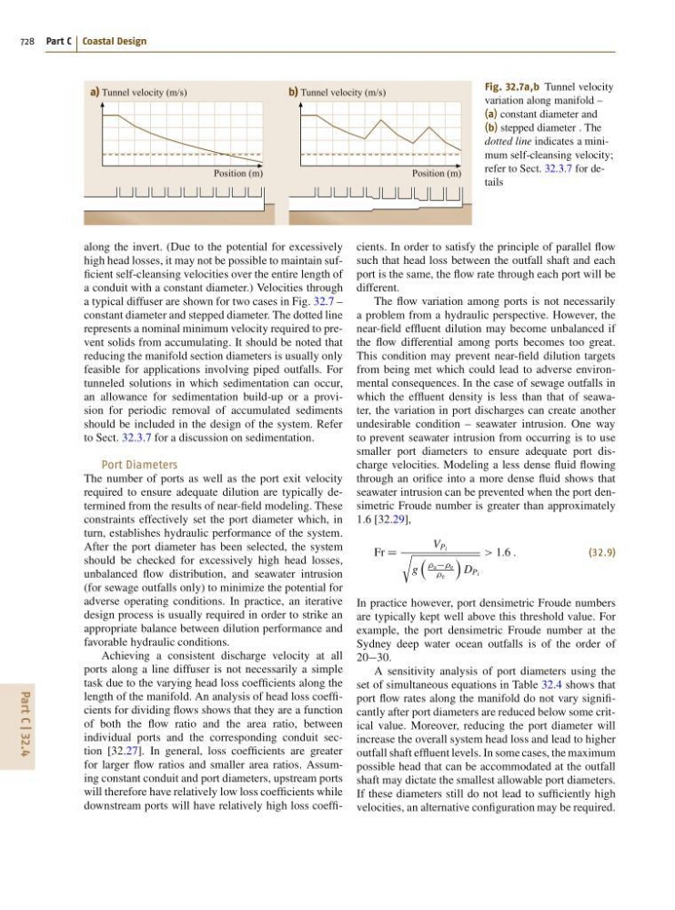
Fig. 32.7a,b Tunnel velocity
variation along manifold –
(a) constant diameter and
(b) stepped diameter . The
dotted line indicates a minimum self-cleansing velocity;
refer to Sect. 32.3.7 for details
along the invert. (Due to the potential for excessively
high head losses, it may not be possible to maintain sufficient self-cleansing velocities over the entire length of
a conduit with a constant diameter.) Velocities through
a typical diffuser are shown for two cases in Fig. 32.7 –
constant diameter and stepped diameter. The dotted line
represents a nominal minimum velocity required to prevent solids from accumulating. It should be noted that
reducing the manifold section diameters is usually only
feasible for applications involving piped outfalls. For
tunneled solutions in which sedimentation can occur,
an allowance for sedimentation build-up or a provision for periodic removal of accumulated sediments
should be included in the design of the system. Refer
to Sect. 32.3.7 for a discussion on sedimentation.
Port Diameters
The number of ports as well as the port exit velocity
required to ensure adequate dilution are typically determined from the results of near-field modeling. These
constraints effectively set the port diameter which, in
turn, establishes hydraulic performance of the system.
After the port diameter has been selected, the system
should be checked for excessively high head losses,
unbalanced flow distribution, and seawater intrusion
(for sewage outfalls only) to minimize the potential for
adverse operating conditions. In practice, an iterative
design process is usually required in order to strike an
appropriate balance between dilution performance and
favorable hydraulic conditions.
Achieving a consistent discharge velocity at all
ports along a line diffuser is not necessarily a simple
task due to the varying head loss coefficients along the
length of the manifold. An analysis of head loss coefficients for dividing flows shows that they are a function
of both the flow ratio and the area ratio, between
individual ports and the corresponding conduit section [32.27]. In general, loss coefficients are greater
for larger flow ratios and smaller area ratios. Assuming constant conduit and port diameters, upstream ports
will therefore have relatively low loss coefficients while
downstream ports will have relatively high loss coefficients. In order to satisfy the principle of parallel flow
such that head loss between the outfall shaft and each
port is the same, the flow rate through each port will be
different.
The flow variation among ports is not necessarily
a problem from a hydraulic perspective. However, the
near-field effluent dilution may become unbalanced if
the flow differential among ports becomes too great.
This condition may prevent near-field dilution targets
from being met which could lead to adverse environmental consequences. In the case of sewage outfalls in
which the effluent density is less than that of seawater, the variation in port discharges can create another
undesirable condition – seawater intrusion. One way
to prevent seawater intrusion from occurring is to use
smaller port diameters to ensure adequate port discharge velocities. Modeling a less dense fluid flowing
through an orifice into a more dense fluid shows that
seawater intrusion can be prevented when the port densimetric Froude number is greater than approximately
1.6 [32.29],
Fr D
V Pi
r
g
ae
e
Á
D Pi
> 1:6 :
(32.9)
In practice however, port densimetric Froude numbers
are typically kept well above this threshold value. For
example, the port densimetric Froude number at the
Sydney deep water ocean outfalls is of the order of
2030.
A sensitivity analysis of port diameters using the
set of simultaneous equations in Table 32.4 shows that
port flow rates along the manifold do not vary significantly after port diameters are reduced below some critical value. Moreover, reducing the port diameter will
increase the overall system head loss and lead to higher
outfall shaft effluent levels. In some cases, the maximum
possible head that can be accommodated at the outfall
shaft may dictate the smallest allowable port diameters.
If these diameters still do not lead to sufficiently high
velocities, an alternative configuration may be required.