

Part C | 32.4
726 Part C Coastal Design
0
ρ e
ρ a
P n
P n–1
z SL
P 2
P 1
T 2
T 1
T n–1
T n
P n
P 2
P 1
T n
T n–1
T 2
T 1
P n–1
Total head line along tunnel
Diffuser (or manifold)
Datum
Head loss between T n and P n
Total head just inside nozzle
Velocity head at nozzle
Total head line for
locations P 1 P n
T n
just upstream of riser
just inside outlet nozzle
just downstream of riser
P n
short distance outside nozzle
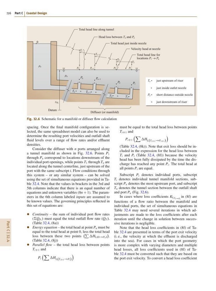
Fig. 32.6 Schematic for a manifold or diffuser flow calculation
spacing. Once the final manifold configuration is selected, the same spreadsheet model can also be used to
determine the resulting port velocities and outfall shaft
fluid levels over a range of flow rates and/or effluent
densities.
Consider the diffuser with n ports arranged along
a tunnel manifold as shown in Fig. 32.6. Points P 1
through P n correspond to locations downstream of the
individual port openings, while points T 1 through T n are
located along the tunnel centerline, just upstream of the
port with the same subscript i. Flow conditions through
this system – or any similar system – can be solved
using the set of simultaneous equations provided in Table 32.4. Note that the values in brackets in the 3rd and
5th columns indicate that there is an equal number of
equations and unknown variables (8n C 1). The parameters in the 6th column labeled inputs are assumed to
be known values. The governing principles reflected in
this set of equations are:
Continuity – the sum of individual port flow rates
(†Q Pi / must equal the total outfall flow rate (Q T /.
(Table 32.4, (8a))
Energy equation – the total head at point P n must be
equal to the total head at point 0, less the total head
loss between these two points
P H L.0!Pn/
.
(Table 32.4, (8j))
Parallel flow – the total head loss between points
T iC1 and
P i
X H L.T iC1 !Pi/
Á
must be equal to the total head loss between points
T iC1 and
P iC1
X
H L.T iC1 !P iC1 /
Á
(Table 32.4, (8k)). Note that exit loss should be included in the expression for the head loss between
T i and P i (Table 32.4, (8f)) because the velocity
head has been fully dissipated by the time the discharge has reached any point P i . The total head at
all points P i are equal.
Subscript P i denotes individual ports, subscript
T i denotes individual tunnel manifold sections, subscript P n denotes the most upstream port, and subscript
T n denotes the tunnel section between the outfall shaft
and port P n (Fig. 32.6).
In cases where loss coefficients K LT i!P i
in (8f) are
functions of a flow ratio between the manifold and
individual ports, the set of simultaneous equations in
Table 32.4 may need several iterations in which adjustments are made to the loss coefficients after each
iteration until the change in solution between successive iterations is negligible.
Note that the head loss coefficients in (8f) of Table 32.4 are presented in terms of the port exit velocity
(i. e., the velocity at which the effluent is discharged
into the sea). For cases in which the port geometry
is more complex with varying diameters and multiple
head losses, all loss coefficients used in (8f) of Table 32.4 must be converted such that they are based on
the port exit velocity. To convert a head loss coefficient