

Part C | 32.1
712 Part C Coastal Design
32.1 Terminology
The following terminology is used throughout this
chapter. Sewage is the raw input to a municipal wastewater treatment plant, the product of which is effluent.
Seawater is the raw input to a desalination plant, the
product of which is brine. Wastewater refers to either effluent or brine. An outfall refers to the disposal system
from the treatment plant to the discharge outlets. The
manifold is that part of the outfall from which there is
a series of offtakes, termed risers. A diffuser comprises
that section of the outfall which includes the manifold
and the risers.
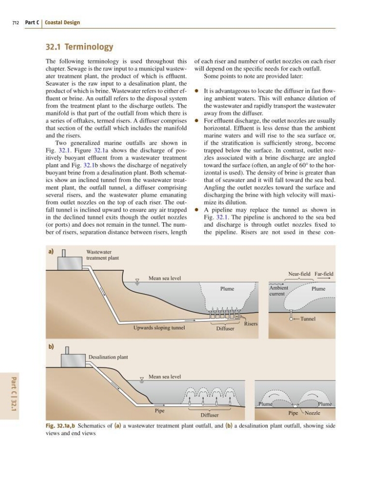
Two generalized marine outfalls are shown in
Fig. 32.1. Figure 32.1a shows the discharge of positively buoyant effluent from a wastewater treatment
plant and Fig. 32.1b shows the discharge of negatively
buoyant brine from a desalination plant. Both schematics show an inclined tunnel from the wastewater treatment plant, the outfall tunnel, a diffuser comprising
several risers, and the wastewater plume emanating
from outlet nozzles on the top of each riser. The outfall tunnel is inclined upward to ensure any air trapped
in the declined tunnel exits though the outlet nozzles
(or ports) and does not remain in the tunnel. The number of risers, separation distance between risers, length
a)
b)
Wastewater
treatment plant
Desalination plant
Ambient
current
Mean sea level
Near-field
Tunnel
Plume
Pipe Nozzle
Plume
Risers
Diffuser
Diffuser
Pipe
Upwards sloping tunnel
Far-field
Plume
Plume
Mean sea level
Fig. 32.1a,b Schematics of (a) a wastewater treatment plant outfall, and (b) a desalination plant outfall, showing side
views and end views
of each riser and number of outlet nozzles on each riser
will depend on the specific needs for each outfall.
Some points to note are provided later:
It is advantageous to locate the diffuser in fast flowing ambient waters. This will enhance dilution of
the wastewater and rapidly transport the wastewater
away from the diffuser.
For effluent discharge, the outlet nozzles are usually
horizontal. Effluent is less dense than the ambient
marine waters and will rise to the sea surface or,
if the stratification is sufficiently strong, become
trapped below the surface. In contrast, outlet nozzles associated with a brine discharge are angled
toward the surface (often, an angle of 60° to the horizontal is used). The density of brine is greater than
that of seawater and it will fall toward the sea bed.
Angling the outlet nozzles toward the surface and
discharging the brine with high velocity will maximize its dilution.
A pipeline may replace the tunnel as shown in
Fig. 32.1. The pipeline is anchored to the sea bed
and discharge is through outlet nozzles fixed to
the pipeline. Risers are not used in these con-