

Part C | 30.3
680 Part C Coastal Design
Horizontal shore
section
Intermediate
sloped section
Outer section
Set shoreward
enough to prevent
flanking
MLW or MLLW
elevation
Slope with
natural profile
Longshore
transport
Natural berm
elavation
Set according
to planned of
Set seaward
to width
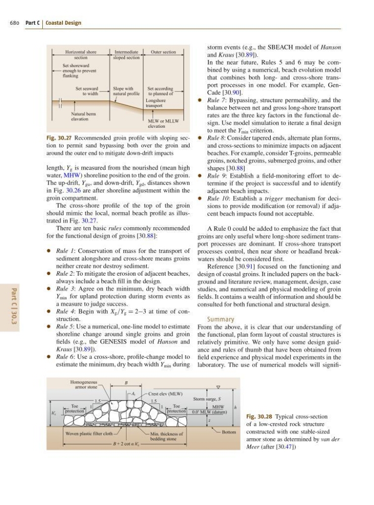
Fig. 30.27 Recommended groin profile with sloping section to permit sand bypassing both over the groin and
around the outer end to mitigate down-drift impacts
length, Y g is measured from the nourished (mean high
water, MHW) shoreline position to the end of the groin.
The up-drift, Y gu , and down-drift, Y gd , distances shown
in Fig. 30.26 are after shoreline adjustment within the
groin compartment.
The cross-shore profile of the top of the groin
should mimic the local, normal beach profile as illustrated in Fig. 30.27.
There are ten basic rules commonly recommended
for the functional design of groins [30.88]:
Rule 1: Conservation of mass for the transport of
sediment alongshore and cross-shore means groins
neither create nor destroy sediment.
Rule 2: To mitigate the erosion of adjacent beaches,
always include a beach fill in the design.
Rule 3: Agree on the minimum, dry beach width
Y min for upland protection during storm events as
a measure to judge success.
Rule 4: Begin with X g =Y g D 23 at time of construction.
Rule 5: Use a numerical, one-line model to estimate
shoreline change around single groins and groin
fields (e.g., the GENESIS model of Hanson and
Kraus [30.89]).
Rule 6: Use a cross-shore, profile-change model to
estimate the minimum, dry beach width Y min during
Woven plastic filter cloth
Homogeneous
armor stone
Toe
protection
Toe
protection
1.5
1.5
1
1
A t
B
B + 2 cot α h′ c
Min. thickness of
bedding stone
Bottom
Crest elev (MLW)
0.0′ MLW (datum)
h′ c
h
z
Storm surge, S
MHW
Fig. 30.28 Typical cross-section
of a low-crested rock structure
constructed with one stable-sized
armor stone as determined by van der
Meer (after [30.47])
storm events (e.g., the SBEACH model of Hanson
and Kraus [30.89]).
In the near future, Rules 5 and 6 may be combined by using a numerical, beach evolution model
that combines both long- and cross-shore transport processes in one model. For example, GenCade [30.90].
Rule 7: Bypassing, structure permeability, and the
balance between net and gross long-shore transport
rates are the three key factors in the functional design. Use model simulation to iterate a final design
to meet the Y min criterion.
Rule 8: Consider tapered ends, alternate plan forms,
and cross-sections to minimize impacts on adjacent
beaches. For example, consider T-groins, permeable
groins, notched groins, submerged groins, and other
shapes [30.88]
Rule 9: Establish a field-monitoring effort to determine if the project is successful and to identify
adjacent beach impacts.
Rule 10: Establish a trigger mechanism for decisions to provide modification (or removal) if adjacent beach impacts found not acceptable.
A Rule 0 could be added to emphasize the fact that
groins are only useful where long-shore sediment transport processes are dominant. If cross-shore transport
processes control, then near shore or headland breakwaters should be considered first.
Reference [30.91] focused on the functioning and
design of coastal groins. It included papers on the background and literature review, management, design, case
studies, and numerical and physical modeling of groin
fields. It contains a wealth of information and should be
consulted for both functional and structural design.
Summary
From the above, it is clear that our understanding of
the functional, plan form layout of coastal structures is
relatively primitive. We only have some design guidance and rules of thumb that have been obtained from
field experience and physical model experiments in the
laboratory. The use of numerical models will signifi-