

Storm Hazard Mitigation Structures 30.2 Coastal Armoring Structures 671
Part C | 30.2
separating plunging, and surging wave breaking and
identifying which formulation to employ in the static
stability analysis.
The Corps of Engineers has a long history of research on the static stability of rubble-mound breakwaters. The Hudson [30.57] formulation was the standard
for many years and is still applied for artificial, concrete
armor-layer units as discussed below.
Melby and Kobayashi [30.58] proposed new, static
stability formulations for plunging and surging waves
on sloping, armor stone structures that depart from
the traditional approach where the primary load variable is the significant wave height H s at the toe of
the structure. In their approach, the maximum, nonlinear wave momentum flux (MF) max as defined by
Hughes [30.59] is employed as the key load variable
in the static stability formulations. The results in Melby
and Kobayashi [30.58] expanded and improved the earlier work in Melby and Hughes [30.60]; utilized the
small-scale physical data from van der Meer [30.26],
and employed the same definitions for S, N z , and P as
originally proposed by van der Meer [30.26]. Two new
coefficients were needed and defined. One coefficient,
a m appears in the final equation, but has two separate formulations, one for plunging and one for surging
waves. The second new coefficient, K s , is added for
an analysis of damage progression and will be further
discussed below. The new, dividing equation separating
the plunging and surging formulations was formulated
to only depend on the structure slope and does not include the permeability parameter P as found in van
der Meer [30.26] and (30.23). The analysis and forTable 30.5 Key coefficients in the van der Meer formulas
Breaker type
Deep water
mean value
Deep water
standard deviation
Shallow water
mean value
Shallow water
standard deviation
Equation
Plunging C pl
6:2
0:4
8:4.H s =H 2% /
0:109
(30.21)
Surging C s
1:0
0:08
1:3.H s =H 2% /
0:109
(30.22)
Surf parameter
m
m1:0
Wave period T
T m
T m1:0
Parallelepiped
block
Grooved cube
(antifer type)
Cube
Tetrapod
Haro
Shed
Cob
Accropod
Dolos
Seabee
Grooved cube
with hole
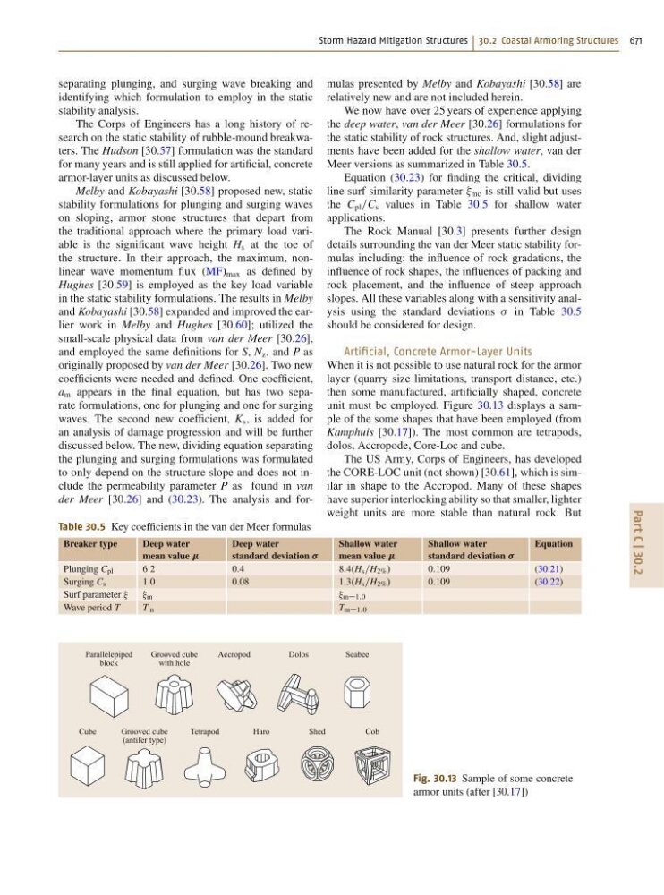
Fig. 30.13 Sample of some concrete
armor units (after [30.17])
mulas presented by Melby and Kobayashi [30.58] are
relatively new and are not included herein.
We now have over 25 years of experience applying
the deep water, van der Meer [30.26] formulations for
the static stability of rock structures. And, slight adjustments have been added for the shallow water, van der
Meer versions as summarized in Table 30.5.
Equation (30.23) for finding the critical, dividing
line surf similarity parameter mc is still valid but uses
the C pl =C s values in Table 30.5 for shallow water
applications.
The Rock Manual [30.3] presents further design
details surrounding the van der Meer static stability formulas including: the influence of rock gradations, the
influence of rock shapes, the influences of packing and
rock placement, and the influence of steep approach
slopes. All these variables along with a sensitivity analysis using the standard deviations in Table 30.5
should be considered for design.
Artificial, Concrete Armor-Layer Units
When it is not possible to use natural rock for the armor
layer (quarry size limitations, transport distance, etc.)
then some manufactured, artificially shaped, concrete
unit must be employed. Figure 30.13 displays a sample of the some shapes that have been employed (from
Kamphuis [30.17]). The most common are tetrapods,
dolos, Accropode, Core-Loc and cube.
The US Army, Corps of Engineers, has developed
the CORE-LOC unit (not shown) [30.61], which is similar in shape to the Accropod. Many of these shapes
have superior interlocking ability so that smaller, lighter
weight units are more stable than natural rock. But