

Part C | 30.2
666 Part C Coastal Design
0
0.2
Quasi-standing
wave
= 1
0.4
F h
*
F h max
F h max
F hq
h b
h s
F hq
t/T
8
6
4
2
0
0
0.1
Slightly breaking
wave
> 2.5
1 <
0.2
F h
*
F h max
F h max
F hq
F hq
t/T
8
6
4
2
0
0
0.1
Impact loads
> 2.5
0.2
F h
*
F hmax
F hmax
F hq
F hq
t/T
8
6
4
2
0
0
0.1
Broken waves
0.2
F h
*
F hmax
F hq
t/T
8
6
4
2
0
Vertical
breakwater
SWL
Small waves
h
*
b < 0.3
H s
* < 0.35
Large waves
0.35 < H s
*
Small waves
H s
* < 0.2
Large waves
0.2 < H s
* < 0.6
Large waves
0.2 < H s
* < 0.6
Moderate berm w.
0.12 < B
* < 0.4
Wide berm
B
* > 0.4
Narrow berm
0.08 < B
* < 0.12
Small waves
with h b
* =
H s
* =
F h
* =
B
* =
0.1 < H s
* < 0.2
Very large waves
H s
* > 0.6
h s
d
High mound
compossite breakwater
SWL
SWL
0.9 < h
*
b < 1
Crown walls
rubble mound breakwater
h
*
b > 1
h s h b
d
Low mound
breakwater
0.3 < h
*
b < 0.6
h s
H d
L h s
B eq
h b
d
High mound
breakwater
0.6 < h
*
b < 0.9
;
;
H s
h s
F h
ρ·g·H b
2
;
B eq
L
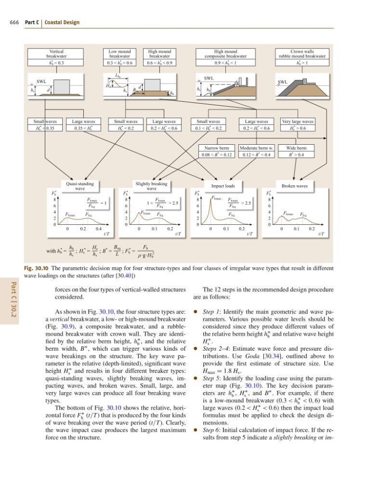
Fig. 30.10 The parametric decision map for four structure-types and four classes of irregular wave types that result in different
wave loadings on the structures (after [30.40])
forces on the four types of vertical-walled structures
considered.
As shown in Fig. 30.10, the four structure types are:
a vertical breakwater, a low- or high-mound breakwater
(Fig. 30.9), a composite breakwater, and a rubblemound breakwater with crown wall. They are identified by the relative berm height, h
b , and the relative
berm width, B
, which can trigger various kinds of
wave breakings on the structure. The key wave parameter is the relative (depth-limited), significant wave
height H
s and results in four different breaker types:
quasi-standing waves, slightly breaking waves, impacting waves, and broken waves. Small, large, and
very large waves can produce all four breaking wave
types.
The bottom of Fig. 30.10 shows the relative, horizontal force F
h (t=T) that is produced by the four kinds
of wave breaking over the wave period (t=T). Clearly,
the wave impact case produces the largest maximum
force on the structure.
The 12 steps in the recommended design procedure
are as follows:
Step 1: Identify the main geometric and wave parameters. Various possible water levels should be
considered since they produce different values of
the relative berm height h
b and relative wave height
H
s .
Steps 2–4: Estimate wave force and pressure distributions. Use Goda [30.34], outlined above to
provide the first estimate of structure size. Use
H max D 1:8 H s .
Step 5: Identify the loading case using the parameter map (Fig. 30.10). The key decision parameters are h
b , H
s , and B
. For example, if there
is a low-mound breakwater (0:3 < h
b < 0; 6) with
large waves (0:2 < H
s < 0:6) then the impact load
formulas must be applied to check the design dimensions.
Step 6: Initial calculation of impact force. If the results from step 5 indicate a slightly breaking or im-