

Underwater Vehicle Manipulators 17.2 Dynamics of Underwater Vehicle Manipulators 409
Part B | 17.2
cle and the other operating the manipulator. One of the
main tasks of the vehicle operator is to keep the ROV as
steady as possible (station-keeping) since the manipulator is attached to the vehicle, and the vehicle motion can
disturb the manipulator and greatly affects the accuracy
of its end-effector interacting with the environment. The
accuracy of the end-effector would be greatly improved
if the manipulator controller could compensate for any
disturbance due to the motion of the vehicle. However,
most commercial ROV systems do not use vehicle motion compensation control for the manipulator that is
directly teleoperated by a human operator. Due to the increase in demand for more dexterous and precise underwater manipulation, many researchers have performed
advanced studies for dynamics and control of underwater vehicle manipulators. Considering the vehicle and the
attached manipulator as one multibody system, several
researchers have studied coordinated motion control of
the vehicle-manipulator system to improve the accuracy
of the end-effector. The coordinated motion control automatically compensates for any disturbance due to the
motion of the vehicle and also takes advantage of the
redundancy of the overall vehicle-manipulator system.
Many underwater tasks require the position accuracy of
the end-effector of the order of a centimeter or subcentimeter, whereas most sensors for the vehicle position
have accuracy of the order of a meter. Therefore, in order
to effectively implement the coordinated motion control
in practice especially in autonomous mode, the sensor
accuracy of the vehicle position must be improved. In
the past, very few AUV systems for intervention missions have been reported and most of them were used as
a testbed for developing autonomous manipulation or as
a working model for research.
17.2 Dynamics of Underwater Vehicle Manipulators
The analysis of the dynamics of underwater vehicle manipulators is much more complex than that of regular
manipulators on the factory floor. For example, it is difficult to accurately introduce the effects of the added
mass and the added moment of inertia in the modeling
process for multiple links of the manipulator. The frictional force and the drag force due to the velocity of the
manipulator itself, waves, and currents are also complex
in modeling. The modeling and control of underwater
manipulators were studied by several researchers, including Kato and Lane [17.9], Dunningan et al. [17.10],
Levesque and Richard [17.11], Mahesh et al. [17.12],
McMillan et al. [17.13], McLain et al. [17.14], Tarn
et al. [17.15], Ioi and Itoh [17.16], Schjølberg and Fossen [17.17], Leabourne and Rock [17.18], Lee and
Choi [17.19], and Ryu et al. [17.20]. In this section,
it is not our intention to derive details of the full
dynamic equations of the underwater vehicle manipulators. Instead, we would like to point out several specific
elements that differentiate underwater vehicle manipulators from regular manipulators.
The hydrodynamic forces acting on a rigid body
moving in fluid can be found in Patel [17.21] and
Troesch and Kim [17.22]. Similar to the vehicle main
body, each link of the manipulator will be influenced by
hydrodynamic forces including added mass, buoyancy
acting at the center of buoyancy (COB) of the link, the
fluid acceleration force resulting from the acceleration
of the fluid itself, and the fluid drag forces exerted on
the link.
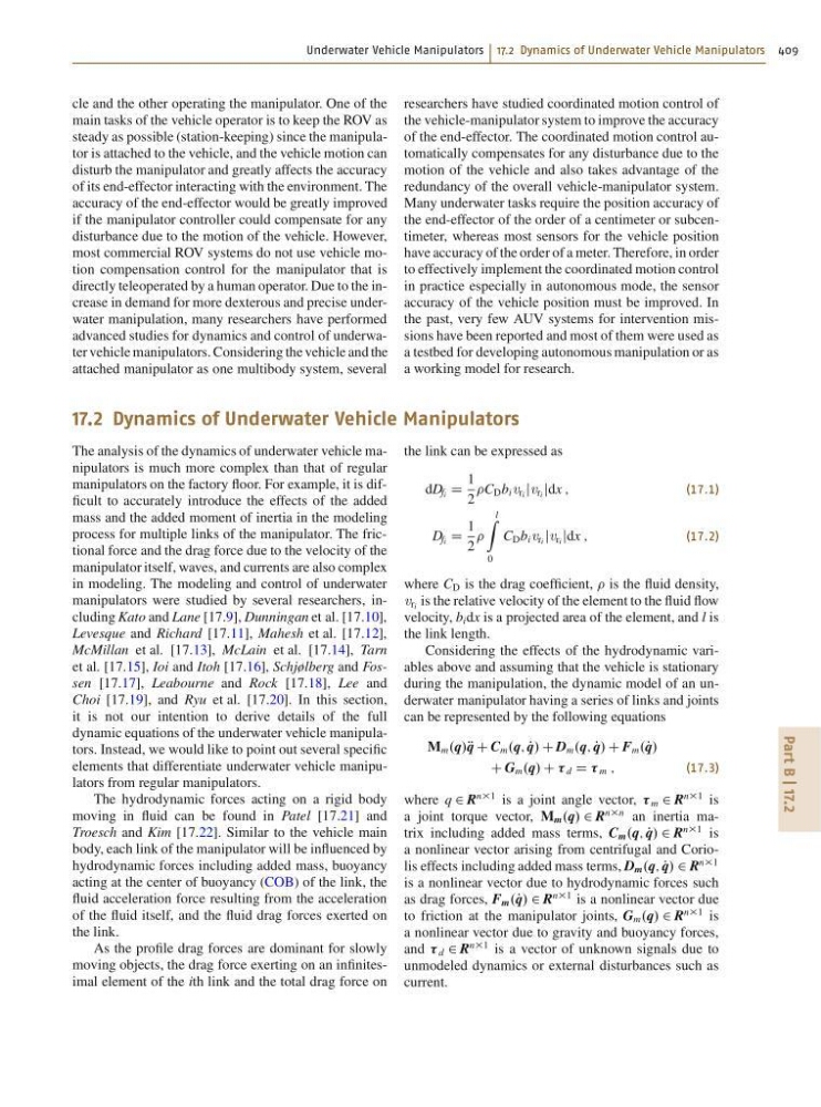
As the profile drag forces are dominant for slowly
moving objects, the drag force exerting on an infinitesimal element of the ith link and the total drag force on
the link can be expressed as
dD fi D
1
2
C D b i v ri jv ri jdx ;
(17.1)
D fi D
1
2
l
Z
0
C D b i v ri jv ri jdx ;
(17.2)
where C D is the drag coefficient, is the fluid density,
v ri is the relative velocity of the element to the fluid flow
velocity, b i dx is a projected area of the element, and l is
the link length.
Considering the effects of the hydrodynamic variables above and assuming that the vehicle is stationary
during the manipulation, the dynamic model of an underwater manipulator having a series of links and joints
can be represented by the following equations
M m .q/R q C C m .q; P
q/ C D m .q; P
q/ C F m .P q/
C G m .q/ C d D m ;
(17.3)
where q 2 R
n1 is a joint angle vector, m 2 R
n1 is
a joint torque vector, M m .q/ 2 R
nn an inertia matrix including added mass terms, C m .q; P
q/ 2 R
n1 is
a nonlinear vector arising from centrifugal and Coriolis effects including added mass terms, D m .q; P
q/ 2 R
n1
is a nonlinear vector due to hydrodynamic forces such
as drag forces, F m .P q/ 2 R
n1 is a nonlinear vector due
to friction at the manipulator joints, G m .q/ 2 R
n1 is
a nonlinear vector due to gravity and buoyancy forces,
and d 2 R
n1 is a vector of unknown signals due to
unmodeled dynamics or external disturbances such as
current.
Part B | 17.2
cle and the other operating the manipulator. One of the
main tasks of the vehicle operator is to keep the ROV as
steady as possible (station-keeping) since the manipulator is attached to the vehicle, and the vehicle motion can
disturb the manipulator and greatly affects the accuracy
of its end-effector interacting with the environment. The
accuracy of the end-effector would be greatly improved
if the manipulator controller could compensate for any
disturbance due to the motion of the vehicle. However,
most commercial ROV systems do not use vehicle motion compensation control for the manipulator that is
directly teleoperated by a human operator. Due to the increase in demand for more dexterous and precise underwater manipulation, many researchers have performed
advanced studies for dynamics and control of underwater vehicle manipulators. Considering the vehicle and the
attached manipulator as one multibody system, several
researchers have studied coordinated motion control of
the vehicle-manipulator system to improve the accuracy
of the end-effector. The coordinated motion control automatically compensates for any disturbance due to the
motion of the vehicle and also takes advantage of the
redundancy of the overall vehicle-manipulator system.
Many underwater tasks require the position accuracy of
the end-effector of the order of a centimeter or subcentimeter, whereas most sensors for the vehicle position
have accuracy of the order of a meter. Therefore, in order
to effectively implement the coordinated motion control
in practice especially in autonomous mode, the sensor
accuracy of the vehicle position must be improved. In
the past, very few AUV systems for intervention missions have been reported and most of them were used as
a testbed for developing autonomous manipulation or as
a working model for research.
17.2 Dynamics of Underwater Vehicle Manipulators
The analysis of the dynamics of underwater vehicle manipulators is much more complex than that of regular
manipulators on the factory floor. For example, it is difficult to accurately introduce the effects of the added
mass and the added moment of inertia in the modeling
process for multiple links of the manipulator. The frictional force and the drag force due to the velocity of the
manipulator itself, waves, and currents are also complex
in modeling. The modeling and control of underwater
manipulators were studied by several researchers, including Kato and Lane [17.9], Dunningan et al. [17.10],
Levesque and Richard [17.11], Mahesh et al. [17.12],
McMillan et al. [17.13], McLain et al. [17.14], Tarn
et al. [17.15], Ioi and Itoh [17.16], Schjølberg and Fossen [17.17], Leabourne and Rock [17.18], Lee and
Choi [17.19], and Ryu et al. [17.20]. In this section,
it is not our intention to derive details of the full
dynamic equations of the underwater vehicle manipulators. Instead, we would like to point out several specific
elements that differentiate underwater vehicle manipulators from regular manipulators.
The hydrodynamic forces acting on a rigid body
moving in fluid can be found in Patel [17.21] and
Troesch and Kim [17.22]. Similar to the vehicle main
body, each link of the manipulator will be influenced by
hydrodynamic forces including added mass, buoyancy
acting at the center of buoyancy (COB) of the link, the
fluid acceleration force resulting from the acceleration
of the fluid itself, and the fluid drag forces exerted on
the link.
As the profile drag forces are dominant for slowly
moving objects, the drag force exerting on an infinitesimal element of the ith link and the total drag force on
the link can be expressed as
dD fi D
1
2
C D b i v ri jv ri jdx ;
(17.1)
D fi D
1
2
l
Z
0
C D b i v ri jv ri jdx ;
(17.2)
where C D is the drag coefficient, is the fluid density,
v ri is the relative velocity of the element to the fluid flow
velocity, b i dx is a projected area of the element, and l is
the link length.
Considering the effects of the hydrodynamic variables above and assuming that the vehicle is stationary
during the manipulation, the dynamic model of an underwater manipulator having a series of links and joints
can be represented by the following equations
M m .q/R q C C m .q; P
q/ C D m .q; P
q/ C F m .P q/
C G m .q/ C d D m ;
(17.3)
where q 2 R
n1 is a joint angle vector, m 2 R
n1 is
a joint torque vector, M m .q/ 2 R
nn an inertia matrix including added mass terms, C m .q; P
q/ 2 R
n1 is
a nonlinear vector arising from centrifugal and Coriolis effects including added mass terms, D m .q; P
q/ 2 R
n1
is a nonlinear vector due to hydrodynamic forces such
as drag forces, F m .P q/ 2 R
n1 is a nonlinear vector due
to friction at the manipulator joints, G m .q/ 2 R
n1 is
a nonlinear vector due to gravity and buoyancy forces,
and d 2 R
n1 is a vector of unknown signals due to
unmodeled dynamics or external disturbances such as
current.