

Autonomous Underwater Gliders 12.6 Discussion and Conclusions 319
Part B | 12.6
Internal
bladder
External
bladder
N E
Vehicle hill
3-way
valve
Check valves
Working fluid
a)
b)
c)
d)
Internal
bladder
External
bladder
N E
Vehicle hill
3-way
valve
Check valves
Working fluid
Working fluid
Transfer fluid
Internal
bladder
External
bladder
N E
3-way
valve
Check valves
Working fluid
Internal
bladder
External
bladder
N E
3-way
valve
Check valves
Heat
Heat
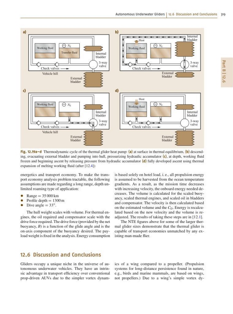
Fig. 12.19a–d Thermodynamic cycle of the thermal glider heat pump: (a) at surface in thermal equilibrium, (b) descending, evacuating external bladder and pumping into hull, pressurizing hydraulic accumulator (c), at depth, working fluid
frozen and beginning ascent by releasing pressure from hydraulic accumulator (d) fully developed ascent using thermal
expansion of melting working fluid (after [12.4])
energetics and transport economy. To make the transport economy analysis problem tractable, the following
assumptions are made regarding a long range, depth unlimited roaming type of application:
Range D 35 000 km
Profile depth D 1300 m
Dive angle D 33
ı .
The hull weight scales with volume. For thermal engines, the oil required and compensator scale with the
drive force required. The drive force (provided by the net
buoyancy, B) is a function of the glide angle and is the
on-axis component of the buoyancy desired. The payload weight is fixed in the analysis. Energy consumption
is based solely on hotel load, i. e., all propulsion energy
is assumed to be harvested from the ocean temperature
gradients. As a result, as the mission time decreases
with increasing velocity, the onboard energy needed decreases. The volume is calculated for the scaled buoyancy, scaled thermal engines, and scaled oil in bladders
and compensator. The velocity is then calculated based
on the estimated volume and the C D . Energy is recalculated based on the new velocity and the volume is readjusted. The results of taking these steps are in [12.1].
The NTE figures above for some of the larger thermal glider sizes demonstrate that the thermal glider is
capable of transport economies unmatched by any existing man-made flier.
12.6 Discussion and Conclusions
Gliders occupy a unique niche in the universe of autonomous underwater vehicles. They have an intrinsic advantage in transport efficiency over conventional
prop-driven AUVs due to the simpler vortex dynamics of a wing compared to a propeller. (Propulsion
systems for long-distance persistence found in nature,
e.g., birds and marine mammals, are based on wings,
not propellers.) Due to a wing’s simple vortex dy-
Part B | 12.6
Internal
bladder
External
bladder
N E
Vehicle hill
3-way
valve
Check valves
Working fluid
a)
b)
c)
d)
Internal
bladder
External
bladder
N E
Vehicle hill
3-way
valve
Check valves
Working fluid
Working fluid
Transfer fluid
Internal
bladder
External
bladder
N E
3-way
valve
Check valves
Working fluid
Internal
bladder
External
bladder
N E
3-way
valve
Check valves
Heat
Heat
Fig. 12.19a–d Thermodynamic cycle of the thermal glider heat pump: (a) at surface in thermal equilibrium, (b) descending, evacuating external bladder and pumping into hull, pressurizing hydraulic accumulator (c), at depth, working fluid
frozen and beginning ascent by releasing pressure from hydraulic accumulator (d) fully developed ascent using thermal
expansion of melting working fluid (after [12.4])
energetics and transport economy. To make the transport economy analysis problem tractable, the following
assumptions are made regarding a long range, depth unlimited roaming type of application:
Range D 35 000 km
Profile depth D 1300 m
Dive angle D 33
ı .
The hull weight scales with volume. For thermal engines, the oil required and compensator scale with the
drive force required. The drive force (provided by the net
buoyancy, B) is a function of the glide angle and is the
on-axis component of the buoyancy desired. The payload weight is fixed in the analysis. Energy consumption
is based solely on hotel load, i. e., all propulsion energy
is assumed to be harvested from the ocean temperature
gradients. As a result, as the mission time decreases
with increasing velocity, the onboard energy needed decreases. The volume is calculated for the scaled buoyancy, scaled thermal engines, and scaled oil in bladders
and compensator. The velocity is then calculated based
on the estimated volume and the C D . Energy is recalculated based on the new velocity and the volume is readjusted. The results of taking these steps are in [12.1].
The NTE figures above for some of the larger thermal glider sizes demonstrate that the thermal glider is
capable of transport economies unmatched by any existing man-made flier.
12.6 Discussion and Conclusions
Gliders occupy a unique niche in the universe of autonomous underwater vehicles. They have an intrinsic advantage in transport efficiency over conventional
prop-driven AUVs due to the simpler vortex dynamics of a wing compared to a propeller. (Propulsion
systems for long-distance persistence found in nature,
e.g., birds and marine mammals, are based on wings,
not propellers.) Due to a wing’s simple vortex dy-